INTRODUCTION This paper presents a theoretical steady state simulation of turboexpander based nitrogen liquefaction cycles [1]23 using the simulation software Aspen Hysys®. A turboexpander based nitrogen liquefier generally consists of a compressor, heat exchangers, turboexpander, J-T Valve. Three types of cycles have been selected for simulation i.e., Claude cycle, modified Claude cycle eliminating the third heat exchanger and modified Claude cycle eliminating the first heat exchanger. Out of these three process cycles one process cycle was selected which will give optimum amount of liquid nitrogen. Again the selected process cycle is simulated to give optimum parameters like pressure of compression, effectiveness of heat exchangers, mass fraction diverted through the turboexpander and efficiency of turboexpander. These parameters will be utilized in designing the components like heat exchangers, turboexpander etc. and also in running condition of the liquefaction plant. |
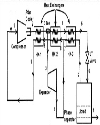
Top DESCRIPTION OF PROCESS CYCLES Case-1: This is a Claude cycle consists of a compressor, a turboexpander, a J-T valve and three numbers of heat exchangers as shown in Figure 1. The compressed nitrogen gas passes through HX-1 (first heat exchanger) and some mass fraction is diverted through the turboexpander, the remaining is passes through the HX-2 (second heat exchanger) and HX3 (third heat exchanger). The isenthalpic expansion is done by using J-T valve. Some amount of liquid is produced and remaining gas passes through HX-3 as cold stream. The cold stream exit from HX-3 mixes with the expanded stream from the turboexpander and again feed to the compressor through HX-2 and HX-1. |
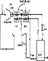
Case-2: It is a modified Claude cycles in which placement of all other components remain same as in Claude cycle except the third heat exchanger. The HX-3 is eliminated as shown in Figure 2. |
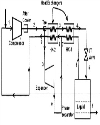
Case-3: It is also a modified Claude cycle in which all components are same as in Claude cycle except the first heat exchanger. Here HX-1 is eliminated as shown in Figure 3. The compressed gas divided into two streams before cooling by any heat exchanger. |
Top ASSUMPTIONS Pressure drop in heat exchangers and pipes are assumed to be negligible. No external heat transfer.
SIMULATION OF PROCESS CYCLES Steady state simulation [4] is done on these three cycles using Aspen Hysys®. Mass flow rate, efficiency of compressor and turboexpander and pinch point of Heat exchanger kept constant for each process cycles and in every simulation. Yield was found out for different pressures of compression (10 bar to 100 bar). |
The input conditions for the process cycles are |
Compressor Mass flow rate =1 kg/s Inlet temperature = 300 K Inlet pressure =1.1 bar Exit pressure (from 10 bar to 100 bar)
After Cooler. Outlet temperature = 300 K
HX-1 (only for case-1 and case-2) Pinch point (minimum temperature difference between two streams of heat exchanger) =5 K
HX-2 Pinch point =3 K
HX-3 (only for case-1 and case-3) Pinch point =1 K
Tee (From where diversion occurs to the turboexpander) Mass fraction (ratio of mass flow diverted to the turboexpander with compressed mass flow) through Turbo expander (change from 0.5 to 1 to get maximum yield)
Turbo expander Efficiency of turbo expander=50% Outlet pressure =1.1 bar
JT Valve Outlet pressure =1.1 bar
Turboexpander efficiency is taken as 50%. Since turboexpander developed so far in India is found to give an efficiency of about 50%. The Plate fin heat exchangers have found to give effectiveness of about 95%-98 %. So pinch point is taken as 5 of HX-1. |
The maximum yield occurs at a particular mass fraction diverted through the turboexpander. |
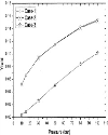
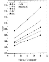
A graph between yield and pressure at exit of compressor is plotted as shown in Figure 4. It shows that under similar operating condition and component specification the yield of case-1 and case-2 is approximately equal. Although yield of all cycles are increasing with the increase in pressure of compression but the yield of case-3 is lowest as compared to the other two process cycles. In case-3 the mass fraction diverted to turboexpander is at higher temperature than the other two cases due to absence of HX-1. The other two heat exchangers HX-2 and HX-3 along with the turboexpander are unable to lower the temperature and produce appreciable amount of liquid. |
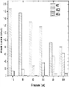
A graph has been plotted to compare the amount heat load of three heat exchangers of case-1 with increasing pressure. The heat load of HX-3 in case-1 is found to be very low (1 kW at 15 bar) as compared to the other two heat exchangers (175.9 kW of HX-1 and 18 kW of HX-2) as shown in Figure 5. So at pressures (10–50 bar) the HX-3 can be neglected. If this is eliminated, it will became case-2 i.e., modified Claude cycle with eliminating the last heat exchanger. |
Among the three process cycles case-3 has very low yield and at low pressures case-2 can give yield of case-1 due to negligible load in HX-3 of case-1. So case-2 is selected as the liquefaction cycles. |
Top PARAMETRIC ANALYSIS OF SELECTED CYCLE Parametric analysis [6] was carried out to optimize the selected process cycle. Following are the key parameters which influences the liquid yield. |
Mass fraction diverted through the turboexpander Effectiveness of HX-1 Pinch point of HX-2 Efficiency of turboexpander Pressure of compression
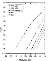
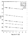
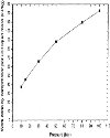
Effect of Mass Fraction diverted through Turbo-expander The effect of the variation of mass fraction through turboexpander on the yield at different operating pressures is studied by keeping the values of turbine efficiency, effectiveness of HX-1 and pinch point of HX-2 constant. From the Figure 6, it is found that yield increases with the mass fraction diverted through turboexpander, and after a certain value it starts decreasing [5]. This is because of insufficient amount of fluid in the high pressure side of HX-2. The yield also increases with increase in pressure. At 8 bar, the maximum yield occurs when 94% of mass diverted through turboexpander. But at 30 bar it occurs when 86 % passed through turboexpander. It means at high pressures, maximum yield can be obtained with less mass fraction diverted through turboexpander. Effect of Variation of Effectiveness of Heat Exchanger 1 The liquid yield increases in direct proportion with the effectiveness of HX-1, for the given efficiency of turbine, expander flow ratio and pinch point of HX-2. With the increase in effectiveness of HX-1, the temperature at exit of high pressure side decreases. This helps to produce more liquid. It is also found that liquid yield is not possible, after certain effectiveness of HX-1 as shown in Figure 7. The lower limit effectiveness of HX-1 decreases with increasing the operating pressure. At 8 bar the lower limit of effectiveness is 0.88. But at 30 bar it is 0.69.If we are operating at high pressures then a low effectiveness HX-1 can be used Effect of Variation of Pinch Point over the Performance of the Plant The liquid yield decreases with increase in pinch point of HX-2, for the given efficiency of turbine, expander flow and effectiveness of HX-1, as shown in Figure 8. Thus pinch point of HX-2 has not effect much on the yield but it should be lower as much as possible. Effect of Efficiency of Turboexpander The effect of turbine efficiency on the liquid yield is shown in the Figure 9. For the given effectiveness of HX-1, pinch point of HX-2 the liquid yield increases with the efficiency of turboexpander. With the increase in efficiency of turboexpander the temperature drop in turboexpander increases. This causes to improve the liquid yield. It is observed that the turboexpander with high efficiency can provide a better yield with lesser mass flow rate through it. With increasing operating pressure the yield also increases. Effect of Pressure of Compression The effects of pressure of compression on yield are shown in Figure 6,7,8,9. Yield increases with increase in pressure of compression. But work required by the compressor to produce unit mass of liquid also increases with increase in pressure as shown in Figure 10. Top CONCLUSIONS After simulation of all the process cycles, it is found that the modified Claude cycle with eliminating third heat exchanger (case-2) is the best. |
At low pressure (10 bar) the work done per unit mass of liquid is less. Also availability of high effectiveness heat exchangers and difficulties in manufacturing turboexpander at high pressures (above 15 bar), the case-2 cycle should select to operate at 8–10 bar. |
Parametric study is carried out on the cycle to access the role of different component efficiencies in predicting overall system efficiency. Operating the case-2 cycle at 8 bar, it is found that, the optimum mass fraction to be diverted through turboexpander for the maximum yield is 0.94. The effectiveness of heat exchanger should be as high as possible (0.98). Pinch temperature of HX-2 should be as low as possible (1K) and turboexpander efficiency must be as high as possible. |
Top Figures | Figure 1.: Schematic diagram of Claude cycle (Case-1)
|  | |
| | Figure 2.: Schematic diagram of modified Claude cycle (Case-2)
|  | |
| | Figure 3.: Schematic diagram of modified Claude cycle (Case-3)
|  | |
| | Figure 4.: Yield at different pressures in the three cases
|  | |
| | Figure 5: Heat load of heat exchangers at different pressures in case-1
|  | |
| | Figure 6.: Variation of yield with the change of mass fraction through turboexpander at different operating pressures
| 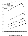 | |
| | Figure 7.: Variation of yield with effectiveness of HX-1 at different operating pressures
|  | |
| | Figure 8.: Variation of yield with pinch point of HX-2 at different operating pressures
|  | |
| | Figure 9.: Variation of yield with efficiency of turboexpander at different operating pressures
|  | |
| | Figure 10.: Variation of compressor work per liquid mass produced with operating pressure
|  | |
|
|