Effect of cryotreatment on the wear performance of tungsten carbide tools Nadig D.S.1, Satisha G.V.1 1Centre for Cryogenic Technology, Indian Institute of Science, Bangalore, 560012 Abstract Success in metal cutting depends upon the selection of the proper cutting tool for a given work material. While, large varities of tools are available, High Speed Steel (HSS) tools and carbide inserts are popularly employed for machining operations. The tool life plays a critical role in the machining operation with regard to quality, time and cost. Cryogenic treatment is being extensively employed to enhance tool life, in particular for HSS tools. In this experimental work, wear resistance properties of tungsten-carbide tool inserts for machining bearing steel (En31) have been studied. After determining the cutting forces, surface roughness and flank wear for different cutting speeds and feed rates, the carbide inserts were cryotreated at 98K for 24 hours in a cryotreatment system followed by tempering at 448K. The tools after cryotreatment have resulted in reduced tool-work interface forces, better surface finish of work piece and increased wear resistance properties. Top Keywords Cutting tools, Wear, Temper, Liquid Nitrogen. Top |
INTRODUCTION The cutting tool industry has evolved over the last half century to the point where an increasing range and complexity of cutting tools are available for metal machining. The major challenge in machining industries lies in achieving high dimensional accuracy, good surface finish and high production rate along with less tool wear. Bearing steel material is used for machine tool components such as slide guide ways, tables, columns, etc, due to its excellent vibration damping characteristics, good machinability, wear resistance and low cost. |
In the recent years, the technology of cryogenic treatment is being extensively employed used in the western countries to impart wear resistance properties to cutting tools especially High Speed Steel (HSS) tools. When the steel tools are exposed to cryogenic temperature for extended time duration during crytotreatment, hard micro sized carbides are released within the atomic structure which fill up the voids between the atoms. These carbides are hard, strong and scratch (wear) resistant and impart wear resistance property to the tool material. During the tempering process post cryotreatment, still finer Nano sized carbides which are harder than the micro carbides precipitate which almost fill up the remaining gaps and voids within the atomic structure. Due to these combined effects of cryotreatment followed by tempering the tool improves the wear resistance property. Improvements in tool life by 200300% have been achieved by cryotreatment for popularly used tools like turning tools of lathes, end mills, hacksaw blades, punches, dies, broaches, copper resistance weld tips, etc. [1] |
So far, sufficient research on the effect of cryotreatment has been carried on HSS tools and the results have been encouraging. However, not enough research studies have been carried on carbide tools which are also widely used in machining activities.[2,3,4] In this experimental research, the effects of cryotreatment on tungsten carbide tools for wear resistance property have been studied. |
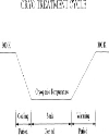
The process of cryotreatment can be broadly termed as exposing the metal samples to low temperature environment for extended duration of time running for several hours. The whole process mainly involves three phases, as shown in figure 1, where the samples are cooled gradually to cryogenic temperature (cooling period), held for extended length of time (soak period) and gradually warmed to room temperature. (Warming period) In a typical cycle, a complete cryotreatment process takes around 38 hours with 5 hours for cooling, 24 hours for soaking and 9 hours for warming. Normally, the cryotreated samples are tempered at higher temperature to further enhance the changes. |
Top EXPERIMENTAL PROCEDURE It was planned to conduct cryotreatment experiments on trials on tungsten carbide tool inserts which are used for machining bearing steel (En31).lt was decided to cryotreat the tools after determining the values of cutting forces, surface roughness and tool wear in order to compare the test results before and after cryotreatment. It was planned to further study the effects of tempering on the cryotreated tools for possible enhancement of wear resistance properties. It was planned to observe the metallurgical changes using the Scanning Electron Microscope (SEM). |
Work pieces measuring 39mm diameter and 200mm length were machined from the raw material viz En 31 (Equivalents 534A99-BS and 52100-A!SI).This material has the chemical composition of 1.00% carbon, 0.50% manganese, 1.4%chromium,0.2% silicon,0.3% sulphur and balance iron. They have the hardness in the range of 58–63 HRC. |
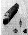
The cutting tools used for the experiments were carbide inserts with V type cutting edge.(Figure 2) These are produced by sintering grains of tungsten carbide in cobalt matrix (to provide toughness) with other materials viz titanium, chromium & molybdenum (to increase hardness). The specifications of the cutting tool are listed in table 1. |
After mounting the tool and the work piece on the lathe machine, the turning operation was carried out for 3 different speeds viz 39.79, 61.23 and 94.29 meter per minute (mpm) respectively. For each speed, alternate combinations of 3 feed rates (0.102, 0.159 and 0.205 mm/rev) and 3 depths of cut (1, 1.5 and 1.5 mm) were selected. All the turning operations were carried for 10 minutes each and the values of cutting forces, surface finish and tool wear. The procedure adopted for determining these experimental data are discussed below. |
Cutting forces The measurement of cutting forces was carried out using IEICOS lathe tool dynamometer. The electronic digital dynamometer incorporates the facility to measure simultaneously three forces. The dynamometer is well designed taking various factors into consideration like exact location of force, the stiffness required and the minimum cross sensitivity, etc. The dynamometer employs latest art of technology in the force measurement using highly stable strain gauge technique. The dynamometer can be directly mounted on the tool post with suitable fasteners. This has been provided with output socket for measurement and recording of cutting forces, which are compressive. The specifications of the dynamometer are as under: Directions of force: OX, 0Y and 0Z Upper limit of force: 1000 Newton Bridge Resistance: 350 ohms Bridge Voltage: 10 Volts max After mounting the dynamometer on the tool post and the work piece between the live and dead centres, the lathe machine was switched on in the plane turning mode, ensuring contact between the tool and work-piece;—The work pieces were turned-for the selected combinations of speeds, feed rates and depths of cut for the duration of 10 minutes. For each trial, the value of cutting force was recorded using the dynamometer. Surface Roughness Surface roughness of the work piece was measured using the surface roughness measuring instrument known as ‘Handy Surf Tester’. This tester has a reciprocating pen stock which has a projecting diamond probe. The diamond probe rubs against the surface of the work piece. The work piece was securely held on a magnetic bed to avoid errors due to side movements. Output readings were recorded continuously on the digital indicator indicating the output in microns. The photo of the handy surf is shown in the figure 3. The textures of tool surfaces were observed using a Scanning Electron Microscope (SEM) with a magnification of 100X.The SEM pictures were obtained in order to carry out comparison with the cryotreated tools. Tool wear Tip Wear of cutting tool was measured using rapid scope. Robust layout of the large rapid scope permits its use in the test shop and machine shop for a wide range of measuring and testing problems. It is suitable for the measurement of various parameters of tools, hobs, punches, gauges, templates, etc. It can carry out thread measurements like profile, major and minor diameters, height of lead, thread angle, etc. In the present application,—the values of-tip wear were measured. Cryotreatment After recording the values of cutting forces, surface roughness and tool wear of the tools; they were cryotreated in the indigenously developed cryotreatment system for 24 hours at 98K with 5 hours of cooling and 9 hours of warm up to room temperature. The entire cryotreatment process took nearly 38 hours consuming nearly 500 liters of LN2. The details of the cryotreatment system are discussed below. The cryotreatment system incorporates mainly a cylindrical cryotreatment unit made out SS304. It has an auxiliary LN2 supply system to supply controlled quantity of pressurised LN2 to the chamber to maintain the rate of cooling, soaking and warm up. The controlled LN2 supply to the chamber is carried out by using a solenoid valve activated by a PID controller. (Figure 4) The cryotreatment unit is made of stainless steel with polyurethane foam (PUF) insulation. It has a fan-motor assembly mounted centrally in the top cover. The tools housed in the meshed trays are gradually cooled to cryogenic temperature by the cold nitrogen gas forced convection continuously produced by the rotating fan housed below the buffer tank containing LN2 and the cold exchange from LN2 circulating in the copper tube heat exchanger brazed on the outer wall of the metallic shroud housed around the meshed trays. The LN2 supply is regulated by a solenoid valve operated by a PID controller with—predetermined—set—points. Various cryotreatment cycles can be programmed to suit the requirements. The temperatures of the specimens are measured using Platinum Resistance Temperature Detectors (RTD). The temperature data of the samples read by PID over the period of the cryotreatment cycle are stored continuously using a data acquisition system. (Figure 5) After the cryotreatment process, a few tool inserts were subjected to tempering at 448 K for one hour and later cooled in air. The tempering procedure was incorporated to observe any possible changes of properties exhibited by cryotreated tools. In order to retain continuity, the tempering process was initiated within two hours after removing the tool inserts from the cryotreatment unit. All the tools (cryotreated and cryotreated followed by tempering) were subjected to the same tests as carried out before cryotreatment to obtain the values of cutting forces, surface roughness and tool wear. These results were compared and analysed. Top RESULTS AND DISCUSSIONS As mentioned earlier, cryotreatment trials were conducted on the carbide inserts and some of them were tempered at higher temperature. The tests were conducted on the tools for the best combinations of cutting speeds, feed rates and depths of cut. Based on the type of trials, the tools were classified into 3 groups viz Untreated (UN), Cryotreated (CT) and Cryotreated followed by tempering (CTT). The details of the results are as under: |
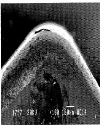
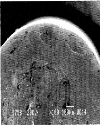
Cutting forces The interface force between the rotating work piece and the tool will be compressive. Reduction in cutting force is always a favourable condition for machining since it reduces the tool penetration force and results in reduced wear of the tool. Apart from this, less frictional heat will be generated with reduced cutting force, resulting in the quantity of coolant. At the same time other possibilities like increased hot hardness of the tool, gumming effect between the tools and work, etc are greatly reduced. The results are shown in table 2 and 3. A significant reduction in the cutting forces for all the cryotreated tools could be observed. This effect was more prominent in the case of cryotreated tools which had undergone tempering after cryotreatment. Even though the results indicated an encouraging trend, it was not possible to predict the repetitiveness for a particular combination of operating parameters due to fewer trials. Surface roughness A smooth surface is always a desired feature of a machined component. Equally a good tool is expected to have a smooth external surface free from craters, damages, irregularities, etc. This ensures enhanced quality of machining. The test results of the finished work pieces are listed in table 4 and 5. Cryotreatment could considerably reduce the surface roughness of the machined components. While it was marginally more in the case tempered and cryotreated tools, it was not possible to predict the exact trend due to fewer triais. The surface roughness of the too! inserts were qualitatively studied using the scanning electron microscope (SEM) with magnification of 100X.The untreated inserts showed higher degree of wear and surface damages compared with the cryotreated inserts which showed comparatively smoother variations in the surface. The SEM pictures Indicate improvements in the surface finish of the cryotreated tools free from cracks, craters, irregularities etc which are shown in Figure 6 and 7. However, no significant changes were observed between cryotreated tools and tempered cryotreated tools. Tool wear Tool wear is the most critical factor for any cutting tool and a minimum wear is highly desirable to enhance the tool life. In the present study, the tips of the untreated tools had chipped off after machining. In the available data obtained using the rapid scope, slight to moderate reduction in tip wear could be observed. This could be attributed to the factor that the tool is mostly packed with carbide particles in the available condition and as such further precipitation of carbides by cryotreatment could not significantly enhance the quantity of carbides density. The results are shown in table 6 and Top CONCLUSION The test results and the SEM pictures indicate improvement in the performance of carbide tools. There is scope for conducting cryotreatment trials on various types of carbide tools in larger lot sizes. |
Top Figures | Figure 1: Cryo-Treatment Cycle
|  | |
| | Figure 2: Carbide tool inserts and the tool holder
|  | |
| | Figure 3: Handy surf with penstock attachment
|  | |
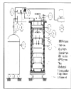
| | Figure 4: Schematic of cryotreatment system
|  | |
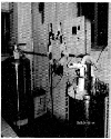
| | Figure 5: Cryo treatment system
|  | |
| | Figure 6: SEM picture of untreated tool insert
|  | |
| | Figure 7: SEM picture of cryotreated tool insert
|  | |
|
Tables | Table 1: Specification of tool holder (HSS) and Carbide inserts
| | Cutting tool | Make: KYOCERA | | Tool Holder | Make: WIDIA | | Working tool geometry | Inclination angle:-6° |
| | | Table 2: Cutting forces of untreated (UN) and cryotreated tools (CT)
| | Cutting velocity(mpm) | Feed rate(mm/rev) | Depth of cut (mm) | Cutting Force (N) | | UN | CT | %change | | 39.79 | 0.205 | 1.0 | -127.5 | -98.1 | 23.5 | | 39.79 | 0.159 | 1.5 | -137.3 | -99.5 | 27.4 | | 39.79 | 0.102 | 2.0 | -170.5 | -137.3 | 19.6 | | 61.23 | 0.102 | 1.5 | -157.5 | -108.1 | 31.3 |
| | | Table 3: Cutting forces of untreated (UN) and cryotreated and tempered tools (CTT)
| | Cutting velocity(mpm) | Feedrate(mm/rev) | Depth of cut (mm) | Cutting Force (N) | | UN | CTT | % change | | 61.23 | 0.159 | 1.0 | -137.4 | -95.36 | 30.6 | | 61.23 | 0.205 | 2.0 | -225.6 | -115.8 | 37.6 | | 94.29 | 0.102 | 1.0 | -157.9 | -98.1 | 37.8 | | 94.29 | 0.159 | 2.0 | -186.3 | -108.1 | 41.9 | | 94.29 | 0.205 | 1.5 | -167.1 | -116.9 | 30.1 |
| | | Table 4: Surface roughness of untreated (UN) and cryotreated tools (CT)
| | Cutting velocity(mpm) | Feed rate(mm/rev) | Depth of cut (mm) | Surface roughness (micron) | | UN | CT | % change | | 0.205 | 0.205 | 1.0 | 3.8 | 2.8 | 26.31 | | 0.159 | 0.159 | 1.5 | 2.8 | 2.5 | 10 71 | | 0.102 | 0.102 | 2.0 | 4 | 2.3 | 43.47 | | 0.102 | 0.102 | 1.5 | 10 | 4.8 | 52 |
| | | Table 5: Surface roughness of untreated (UN) and cryotreated and tempered tools (CT)
| | Cutting velocity(mpm) | Feed rate(mm/rev) | Depth of cut(mm) | Surface roughness (micron) | | UN | CTT | %change | | 0.159 | 0.159 | 1.0 | 4 | 2.09 | 47.75 | | 0.205 | 0.205 | 2.0 | 4.1 | 1.9 | 53.65 | | 0.102 | 0.102 | 1.0 | 3.23 | 2.5 | 22.6 | | 0.159 | 0.159 | 2.0 | 4.29 | 1.8 | 58.04 | | 0.205 | 0.205 | 1.5 | 4.3 | 1.8 | 58.13 |
| | | Table 6: Tool wear values of un treated (UN) and cryotreated tools(CT)
| | Cutting velocity(mpm) | Feed rate (mm/rev) | Depth of cut (mm) | Tip Wear(micron) | | UN | CT | | 0.205 | 0.205 | 1.0 | Broken | 0.78 | | 0.1Ò9 | 0.159 | 1.5 | Broken | 0.80 | | 0.102 | 0.102 | 2.0 | 0.89 | 0.78 | | 0.102 | 0.102 | 1.5 | Broken | 0.69 |
| | | Table 7: Tool wear of untreated (UN) and cryotreated tools after tempering (CTT)
| | Cutting velocity(mpm) | Feed rate(mm/rev) | Depth of cut(mm) | Tip Wear (micron) | | UN | CTT | | 0.159 | 0.159 | 1.0 | 0.79 | 0.76 | | 0.205 | 0.205 | 2.0 | Broken | 0.67 | | 0.102 | 0.102 | 1.0 | 0.80 | 0.59 | | 0.159 | 0.159 | 2.0 | Broken | 0.78 | | 0.205 | 0.205 | 1.5 | Broken | 0.47 |
| |
|