INTRODUCTION Large-scale helium liquefaction/refrigeration plants are used to absorb heat loads in kilowatts range at temperatures 5 K and below for cooling superconducting magnets, RF cavities etc. in installations like Particle accelerators, Colliders and Fusion devices 14. The major purpose of those large-scale cryogenic facilities are to provide cooling or refrigeration at different temperatures starting from 80 K to as low as 1.8 K. For example, LHC, the largest particle accelerator, use super-fluid helium at 1.8 K for refrigerating the superconducting magnets used in the accelerator 7, The capacities of those large-scale helium liquefier/refrigerators range from a few kW to tens of kW. The heat loads are usually of steady state and/or dynamic in nature with different time-temperature profiles, amplitudes and frequencies [2,3,5], |
Along with steady state analysis, the plants with some specific applications like fusion devices or RF cavities are subjected to the pulsed heat load generated out of the operation of the superconducting magnets in a pulsating operational regime [16,19]. The heat ioads are pulsating in nature as well as have different frequency and amplitude. Therefore, it may be stated that the role of cryogenic facilities is to satisfy different cooling needs with stringent cooling requirements and the challenge lies into proper mitigation of dynamic heat loads generated from the applications [2,3]. Transient analysis helps in design of large-scale helium plants through improved understanding of the processes leading to a better design that reduces the cool-down and warm-up time, and optimizes their operations and controls for different transient scenarios [1,3,5,8-19]. Appropriate strategies for mitigating the effects of fluctuating heat loads such as pulsed heat load in fusion devices can be obtained through understanding of the system dynamics [15,16,19], |
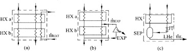
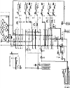
Basic cycle for helium liquefier Kamerlingh Onnes, in 1908, first liquefied the helium gas by pre-cooling the high pressure gas using liquid nitrogen and liquid hydrogen and finally expanding that precooled and high pressure gas through Joule-Thomson valve 20. Later the technology has been improved and use of expansion devices such as expansion engines and turbines together with liquid nitrogen pre-cooling improves the plant performances [2-1]. However, the basic constructional blocks remain the same for the helium liquefier/refrigerator systems. The basic constructional blocks are pre-cooling by liquid nitrogen (Figure 1(a)), reverse Brayton cycle constituting expansion engine or turbine and heat exchanger (Figure 1(b)), and simple Linde cycle (Figure 1(c)) having expansion devices such as J-T valve and heat exchanger. The first of these kinds of plant was built by Collins in 1946 20. He used two expansion engines together with the Linde cycle to liquefy helium 20. The state-of-the-art helium liquefiers/refrigerators of these days also use different combination of the basic blocks, however, with some modifications due to the requirements of the applications. Large-scale helium liquefier/refrigerator While Collins cycle is the fundamental cycle for helium liquefaction, the cycles for large-scale systems have thermodynamically more involved configurations with a large number of components like heat exchangers and expanders arranged in apparently complex manner depending on the demands and constraints imposed by the applications such as, the cooling requirements, cost, size, power consumption, reliability etc. [3,4,6,7], For the same load requirements, several alternative designs exist in the topology of the cycle that often includes devices like cold compressor, wet expander etc., which are special to helium systems [2,6,7], A typical large-scale helium liquefier has been shown in Figure 28, This is used in the fusion device, LHD, Japan 8, It may be observed that the plant design is complex and consists of all three of the basic building blocks as mentioned in the preceding section. In general, all the existing and state-of-the-art plants are thermodynamically complex having large number of components including wet expanders, cold compressors, ejectors etc. These plants are highly energy intensive and therefore, configurations are varying in terms of number of expanders and arrangements, heat exchangers, pressure levels and temperature stages. A detail study on the existing systems may be found in 2, However, it is worthy to mention here that due to the thermodynamic complexities of the cycles and large number of components, analysis of those cycles for more effective energy utilization and higher Carnot COP simulation is the only option. Therefore, selection of the simulator for the purpose of analysis of these cycles is important. In the next section, the purpose, issues and tools required for simulation of helium systems have been discussed. A comparative study between different simulators has also been presented. Top OBJECTIVE OF THE PAPER Design and simulation of large and complex process plants demand use of process simulator that helps in modeling and simulation. While attempts have been made to evolve a dedicated simulator for helium plants, a more popular approach is to use general purpose process simulators that are employed in designing chemical plants [17-19]. However, these commercial process simulators need to be customized for design and analysis of helium systems with regard to appropriate Equation of State for thermodynamic properties of the fluid, appropriate models for transport and thermophysical properties of helium and the structural materials, characteristics curves of the equipment used etc. Apart from the above requirements, availability of options in the process simulator for some thermodynamic and mathematical tools like the Second Law analysis, Exergy/availability analysis, optimization routines, and algorithms for solving simultaneous differential-algebraic equations and advanced controls etc. are desirable. In this paper some of the popular commercial general purpose process simulation software have been explored to find out the suitability for simulation of helium liquefaction/refrigeration systems with minimum requirement of customization. |
Top PROCESS SIMULATION OF HELIUM SYSTEMS Process simulation is used to study the intertwined effects of different process parameters and accordingly to design the process including selection of operating parameters, controls etc. Existing processes may be analyzed using processes simulation in order to enhance the performance of the process as well as up-gradations. Besides, off-design conditions also may be analyzed for performance prediction of the process before the original plant has been installed. As mentioned in previous sections, the helium liquefier/refrigerator systems are thermodynamically complex and use critical components such as cold-compressors, wet expanders etc. Therefore, process simulation helps in analyze the plants for off-design performances, optimization of the parameters in the light of technological-economic constraints. |
Issues in steady state simulation Modeling processes where there are more than one recycle (guess or tear) streams like in the case of the simulation of nitrogen plants based on Claude cycle or helium plants, is difficult. Simulation of Linde based plants is comparatively easier as it has only one recycle stream. Convergence of solution as well as the time taken is highly dependent of the initial guess values provided as the recycle stream parameters. Use of rigorous property generation models for more accurate solution, demands more computation time and effort. The convergence of solution depends on the flow-sheeting algorithm, type of solver, convergence acceleration method, tolerance etc and the proper selection/specification of the above factors decides not only the convergence but all its speed, accuracy and repeatability. The specification of certain components may have to be performed in an indirect way in many cases. For instances, to specify screw compressors, their isothermal efficiency has to be provided in terms of either adiabatic or polytropic efficiency which is the conventional way. Heat exchanger effectiveness may have to be provided in terms of ‘minimum temperature approach’ in Aspen HYSYS. The simulator should be capable of modeling of special components in a particular field such as wet expanders, cold-compressors etc. in helium refrigerators/liquefiers. Flow-sheeting and specification of components have to be correctly done in order to avoid under specified or over constrained situations. When performing parametric studies on processes which require more number of recycles, the step size for increment or decrement is very significant and the proper selection of it decides the convergence. This problem has to be intelligently tackled when performing optimization studies using revolutionary methods like genetic algorithm (GA) where the prediction of the new set of inputs to the simulation is randomized. When using commercial process simulator, user defined functions or variables have to be provided to perform analysis based on exergy, entropy generation minimization etc. Also, in some case it may be necessary for the user to specifying more accurate property values in certain special thermodynamic zones like critical region or in some instances where the default property method is not giving accurate property data etc. In order to understand the interdependent relationships among parameters using a commercial simulators, common tools like sensitivity analysis, data book, spread sheet, adjust, set etc may be intelligently used to their intertwined effects have to be modeled. Optimization of the processes with the constraints related to techno-economical considerations using commercial process simulators may sometimes require the customization of the simulator or the interfacing of the simulator with other programming software like Matlab™, C, C++, VB®, MS™ Excel® etc.
Issues in process plant design: Applications of dynamic simulation Dynamic simulation can be used for the following applications. Simulation for the analysis of off-design performance of plants to reduce the cost of the plant. Operability and safety analysis of the plants. Optimization of large transients like cooldown, warm-up processes. Controllability study for the process control structure. Analysis of the plant performance during the scenarios like pulsed heat load, superconducting magnet quench etc. and determining suitable cycle alternatives. Performance analysis during the change in operating mode from pure liquéfier to pure refrigerator or mixed mode of operation etc. Operator training for better supervisory control and maintenance.
A simulator should have the requisite tools to take care of the above requirement of steady state and dynamic simulations. Tools for simulation Tools required for performing the simulation in both steady state and dynamics are listed as follows: Equipment design and sizing modules. Mass, energy, momentum balance equations and the First Law, the Second Law and exergy analysis tools. Thermodynamic and transport property models for helium like equations of state (EOSs). Thermo-physical properties of materials of construction. Tools for parametric study, optimization both in steady state and dynamics. Extensibility and interface with external software tools like Excel®, plotting software like Origin™ etc. Tools for customization of the models used in the software. Flexibility in attachment of property data, user defined variables, functions etc., in specifying special equipment, in performing thermo-economic analysis as well as optimization studies.
Different approaches for process simulation of helium systems For the purpose of simulation one may either write a computer code or may use any commercially available software and customize it for the specific purpose. Writing own code has” some advantages and disadvantages over using commercial simulators. Advantages: Versatility or the capability to model different types of processes Better control over the simulation process. Ease of modification and customization of models. Rigorous modeling of the equipment.
Disadvantages: It is time consuming and needs reengineering for modeling the equipment. Versatility is less compared to the commercial process simulators. Not standardized for interfacing with other software.
Primarily the option of using commercial simulators has been chosen. The issues related to the process simulation in steady state and dynamics have been presented in the next section. Comparison between commercially available general purpose process simulators A number of process simulators are used for simulation of helium liquefier/refrigerator plants. For example, Maekawa et al. [5,8,10,12] used Visual Modeler® (VM®) and customized it for simulation (C-PREST). Bradu et al. [13,14] incorporated their own models and used the solver of EcosimPro® etc.Besides, SPEED-UP®, DSS/2®, OPTISIM®, all commercial process simulators are used for the purpose of steady state as well as dynamic simulation of helium liquefier/refrigerator plants [10,11]. However, many of the above mentioned simulators used where customized ones for helium simulation and hence, were not available commercially. Hence, we have made an attempt to use some commercially available process simulators, which are generally employed for the simulation of chemical and petro-chemical processes. Out of the different commercial process simulators, we have selected Aspen Hysys®, Aspen Plus®/Dynamics®, and ChemCAD®. A comparative study has been performed to evaluate the potential of those simulators to be served our purpose. Table 1 illustrates the results of the comparison. It may be observed from Table 1 that Aspen Hysys® is the only simulator that provides the MBWR EOS for helium which can accurately generate property data up to 2.2 K 17. Besides, the ease of generating flow-sheet and transferring cases from steady state to dynamics is another advantage of Aspen Hysys® than rest of the simulators. We have selected Aspen Hysys® for these above mentioned reasons and some more as: Numbers of tools for steady state studies. Easier user-interface for specifying components and streams. Component sizing in dynamics. Availability of advance control algorithms. Logical operators and spread sheet. Event scheduler and Optimizer and neural parametric analyzer. Easy customization of the models and property data. Dynamic assistant for specifying the boundary conditions.
IIT Kharagpur approach For the purpose of analysis of large-scale helium liquefiers/refrigerators, Aspen Hysys® has been selected as the simulation tool for both steady state and dynamics cases. However, being a general-purpose simulator, customizations were required to fulfill the requirements of the study. For example, to perform exergy based analysis, user-defined variable has been attached to each stream for calculating the exergy values. In fact for specifications of some of the components like screw compressors, heat exchangers etc, have to be provided in an indirect way. Parametric studies in steady state have been performed using various tools such as data book, set and adjust. Customization has been performed to include variation of convective heat transfer co-efficient of each stream in heat exchanger with respect to the mass flow rate. For the expanders including turbine and expansion engines, the correlations for capacity with respect to inlet temperature, pressure, density and compressibility factor has been incorporated using spread-sheet. Also the characteristics curves for the expanders also have been incorporated to rate the expanders. It has been observed that the thermo-physical properties of material of construction are considered as constant in Aspen Hysys®. Therefore, the variation of those properties has also been added by automation using Excel® VBA®. The simulator has been validated by simulating two actual plants and comparing the simulation results with actual plant data. The details of validation of Aspen Hysys® for helium plant simulation and customization performed for the same have been published elsewhere 18. The equipment models in Aspen Hysys® have been validated for a temperature range from 300 K to 2.2 K in helium plants by Deschildre et al. 17. The customized simulator has been employed for the purpose of the analysis and design of large-scale helium liquefiers/refrigerators. The future plan includes analysis helium liquefier/refrigerator cycles to understand the effects of the pulsed heat load. The pulsed heat load is typical during the operation of the fusion devices and the helium liquefier/refrigerator employed in fusion devices cannot be subjected to such varying heat loads. Hence, this necessitates techniques to absorb or mitigate the adverse effects of pulsating load on the helium liquefier/refrigerator employed. Different pulsed load mitigation methods may be suggested and evaluated on models of actual plants to understand their efficiency. This calls for the rigorous control strategies and control mechanisms to ensure a stable operation. All these aspects will be studied using Aspen Hysys®. It may be seen from the table 1 that, Aspen Plus is another potential simulator which may be used for the simulation studies on helium plants. Some of the benefits which Aspen Hysys does not provide are Tools for Exergy analysis Tools for parameter estimation Dynamic optimization
The only drawback of this simulator is the unavailability of accurate equation of state for helium that provides the accurate data over the range of operation of helium liquefier/refrigerator. Therefore, efforts are being made to incorporate user-defined property data from specific property packages for helium like HEPAK™. Finally, as it has been seen that it required a lot of customization to use a general-purpose simulator for helium application, efforts are also being made to develop in-house simulator dedicated for helium systems, which will have all the required equipment models, facilities for accurate property generation, special tools for parametric studies, exergy based analysis and optimization studies. Top CONCLUSION The helium liquefaction/refrigeration systems are peculiar in terms of their wider operating temperature range, involvement of large number of components, special devices, properties of helium, properties of construction materials at very low temperatures etc. While performing steady state as well as dynamic simulation of helium liquefiers/refrigerators these factors have to be addressed. However, many of these aspects are not taken care of by most of the general-purpose process simulators. In this paper, some of the commercially available software have been compared on the basis of their suitability for addressing the above issues and Aspen Hysys® has been chosen for our simulation studies. The areas, methodology and the extent of success that have been achieved in customizing the software, Aspen Hysys®, for simulation of helium systems have also been discussed. Different approaches adopted by NT Kharagpur have also been discussed in the present work. |
Top ACKNOWLEDGEMENT Financial support by IPR, Gandhinagar, India through a project under National Fusion Program (NFP) is gratefully acknowledged. |
Top Figures | Figure 1.: Basic stages of helium liquefier/refrigerators: a) Pre-cooling stage, b) reverse Brayton cycle, c) Linde cycle.
|  | |
| | Figure 2.: Helium liquefier of LHD, Japan 8
|  | |
|
Table | Table 1: Comparative study on different process simulators
| | Required Tools | Aspen Plus®/Dynamics® | Aspen Hysys® | ChemCAD® | | Thermodynamic and Transport Property Data for Helium (MBWR EOS) | No | Yes | No | | Tools for Exergy Analysis | Yes | No | No | | Flow-sheeting Algorithms | Equation Oriented Method | Yes | Yes | Yes | | Sequential Modular Appr. | Yes | No | Yes | | Parametric Study | Yes | Yes | Yes | | Logical Operators, Recycle | No | Yes | No | | Higher Order Numerical Methods | Yes | No | Yes | | Dynamic Optimization Tools | Yes | No | No | | Ease of Transfer from Steady State to Dynamics | No | Yes | Yes | | Event Scheduler for Implementation of Sequence of Operation | Yes | Yes | No | | Parameter Estimation | Yes | No | Yes | | Plate-fin HX Model | Yes | Yes | No | | Tabular Property Data | No | Yes | No | | CAPE-OPEN™ | Yes | Yes | Yes | | Customization Tools | Yes | Yes | No | | Interface with Other Software | Yes | Yes | Yes | | Spread-sheet | No | Yes | No |
| |
|