|
|
|
|
Simulation tool for determining dynamic characteristics of high speed cryogenic rotor bearing systems by comparison with experiments Arun S.1, Jadhav Mohananand1, Chakravarty Anindya1, Singh Trilok1 1Cryotechnology Division, Bhabha Atomic Research Centre, Mumbai-85 Abstract Most cryogenic turboexpander rotors are gas bearing supported high speed machines with a small size turbine at one end and a brake compressor at the other end. It is important to correctly predict the critical speeds of these rotors to enable them to quickly pass through these speeds during coasting up to design/service speed and also to define the stable operation band sufficiently far from the cntical speeds. The present paper describes the development of a simulation tool for correct determination of the dynamic characteristics of a rotor bearing system. Transfer matrix method is used in the program for computing the dynamic characteristics. Top Keywords Turboexpander, Critical speed, Stiffness, Transfer matrix method, Synchronous vibration response plot. Top | Introduction Most modern cryogenic refrigerators and liquefiers are based on very high speed turboexpander rotors consisting of a miniature turbine at one end and a brake compressor at the other. For such high speed machines, it is imperative to know the exact dynamic characteristics so as to avoid running the rotor for a prolonged period near one of its critical speeds or to decide on the design speed to be sufficiently away (on the lower side) from the first bending critical speed. In most cases, the actual dynamic characteristics of the rotor bearing system are determined during laboratory trials [1, 2], The radial stiffness characteristics of the rotor bearing system is dependent to a large extent on the actual operational clearance of the journal bearing system, thus in turn affecting the actual critical speed band of the rotor bearing system. Thus, a series of experiments with different radial bearing clearances would generate different vibration signature bands through FFT analysis. However, to translate the signature to stiffness data corresponding to different radial bearing clearance requires a mathematical tool. The present paper describes the development of such a tool based on Transfer Matrix Method (TMM) [3, 4] where the actual rotor geometry, inertia properties and residual unbalance are taken into account to generate the unbalance response at various rotor stations at different speeds. It is possible to vary the input stiffness and damping characteristics in the tool to generate a vibration signature similar to the actual rotor bearing system. Apart from the determination of dynamic characteristics, some other important parameters such as actual service clearance between the turbine and its diffuser at various speeds leading up to the design speed can also be computed. All of these are expected to reduce design and development cycles of similar rotors in future. |
Top Rotor model using transfer matrix method (TMM) Transfer matrix method, developed by Myklestad and Prohl consists of modeling the entire shaft as a finite number of lumped inertia elements (disks) connected by mass less elastic shaft sections [4], Field variables at any section common to the two elements consist of deflection w, slopeʸ, bending moment My and shear force Vz, for bending in the x-z plane (The axes system selected is shown in Fig. 1), x-axis being the bearing axis. The corresponding variables in the x-y plane are v, Mz and Vy. The idea is to relate the field variables at either sides of the mass or shaft element through equilibrium equations. These relations are expressed in matrix form. The matrix corresponding to the inertial or mass element is called point matrix and that corresponding to the elastic or shaft element is known as field matrix. The point and field matrices can be multiplied in order from one end of the rotor to the other end to get the overall transfer matrix. The overall transfer matrix thus relates the field variables at the left end of the rotor to that at the right end. The gyroscopic effects are also considered for the analysis. The overall transfer matrix developed for the tool which is of size 17×17 takes into account the unbalance forces, gyroscopic effects and the forces due to direct and cross coupled bearing stiffnesses and damping and is thus in the most general form. |
The field matrix relationship for the ith shaft element can be expressed as [4]: |
where w and v are the deflections of the rotor Øin the z and y directions respectively, ɵ and Ø are the slopes of the rotor in the x-z and x-y planes respectively, My and Mz are the bending moments in the x-z plane and x-y plane respectively and and are the shear forces in the z and y directions respectively. The subscript ‘c’ and ‘s’ refer to cosine and sine components of the corresponding variable. |
Equation (1) can be written in a simplified manner as [4]: |
The point matrix relationship for the ith mass element is given by [4]: |
Where the subscript i stands for the mass element number and the superscript L or R denotes whether the field variables are for the left or right hand side of the mass element. [P]i is a 17 × 17 matrix with the following elements [4]: |
where lT and lp are the transverse and polar moments of inertia of the ith mass element of mass mi, ω is the rotational speed of the shaft, kzz and kyy are the direct stiffnesses in the z and y directions respectively, and czz are the direct damping coefficients in the z and y directions respectively, kzz and kyy are the cross coupled stiffnesses in the z and y directions due to deflections in the y and z directions respectively, czz and cyy are the cross coupled damping coefficients in the z and y directions due to deflections in the y and z directions respectively and uzi and uyi are the unbalances associated with the ith mass element in the z and y directions respectively. All the other elements of this sparse matrix are zeros. |
By multiplying the field and point matrices in order, the overall transfer matrix, which relates the variables on the right most end of the rotor with those on the left most end, can be obtained. Denoting the overall matrix as U, the equilibrium equation connecting the field variables or boundary conditions at the left, {S}0and right end, {S}n+1 of the rotor is expressed as [4]: |
 |
By applying proper boundary conditions to the overall transfer matrix relation, the response of the rotor to the given unbalance can be determined. The unbalance response at any station is determined as a function of the rotational speed to get the synchronous vibration plot from which the critical speeds of the shaft can be obtained [4,5], A computer program is developed based on this analysis to determine the unbalance response of the rotor. The program also has a facility to directly compute the critical speeds without going into the unbalance response. The program developed is validated by analyzing the response of a simple cylindrical shaft with freefree boundary conditions [6]. |
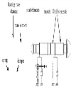
Top The Turboexpander rotor The analysis is now extended to the transfer matrix model of a turboexpander rotor shown in Fig. 1. |
The rotor model is divided into a large number of inertial-elastic element pairs. The turbine and the compressor are modeled with shaft elements of shorter lengths to take care of their geometry. However, the rotor portion is modeled with comparatively longer shaft elements since their cross section does not vary over a relatively larger length. Both the bearing areas of the rotor are modeled as a single mass and shaft element each. Thus the entire stiffness and damping offered by each of the two gas dynamic bearings are associated with a single mass element representing the mass of the bearing area. The rotor under consideration is having a free-free boundary condition. |
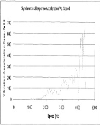
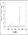
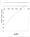
Top Experiments with the Turbo-expander Rotor A number of experiments are done on the various units of 16mm turboexpander rotor to determine the critical speeds. Vibration signature from one such trial run is plotted in Fig. 2. The curve shown is obtained from the Fast Fourier Transform of the response of an accelerometer attached to the rotor housing while the rotor is made to accelerate from zero speed to its design speed of 4500 Flz under steady state conditions (where the speed of the rotor is raised slowly). The synchronous response is plotted in terms of acceleration due to gravity, “g” as a function of rotor speed. |
From Fig. 2, it is clear that the response is increasing with increase in rotational speed. The amplitude of acceleration has local maxima at speeds around 2300 Flz, 3000 Flz, 3500 Flz, 3800 Flz and 4100 Flz. The peak around 4100 Flz is sharp and is very well defined. Also, it can be observed that most of the peaks are split into pairs. It is clear from the graph that one of the rigid bearing critical speeds is around 4100 Hz. |
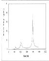
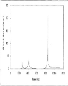
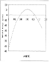
Top computation of bearing dynamic characteristics Since the experiments show the existence of a critical speed at around, 4100 Hz, the direct stiffness values (user inputs) in the simulation tool are adjusted so that the synchronous vibration plot from simulation also peaks around 4100 Hz. The computed radial stiffness values are practical only when the peak is assumed to concur with the second bearing critical. Moreover, bearing symmetry is assumed in the model and cross coupled stiffness and damping coefficients are neglected. With all these assumptions, the direct radial stiffness comes out to be 33 N/μm, which seems reasonable from the order of magnitude point of view [7], The Synchronous response plots showing the whirl radius at the turbine end of the rotor for the same value of stiffness and for a damping coefficient of 100 Ns/m are shown in Fig. 3. The third critical speed, which is in fact the first bending critical, can also be observed in the plot. The first bearing critical speed, which was not clearly identifiable in the experiments, is obtained as 2259 Hz. The third, which is a bending mode critical speed, is at 7787 Hz. |
In order to increase the accuracy of the results, the number of elements is increased. So the same analysis is repeated for a new model where the entire rotor is divided into 64 inertial-elastic element pairs. Each of the two bearing areas is modeled as 8 inertial-elastic element pairs and the stiffness and damping are distributed over the whole bearing length. The turbine and compressor, however, are modeled as similar to that in the first model. |
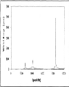
The synchronous response plots for different values of damping coefficients are shown in s Fig. 4, 5 - 6. These graphs show the synchronous response at the turbine end of the rotor for different values of bearing damping coefficients. |
Using this more accurate model, the value of direct stiffness is obtained as 36 N/μm and the first and third critical speeds can be seen slightly shifted to the right to 2640 Hz and 8339 Hz respectively. |
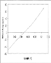
The turbine diffuser radial clearance in the assembly is kept at around 85 μm. For the present rotor bearing configuration, a lower radial clearance would produce metal to metal contact (and consequent high frequency vibrations) between the turbine and the diffuser especially while trying to pass through the second critical speed around 4000 Hz [1], Thus, the whirl amplitude at the turbine region is about 85 μm. Through simulation, it can be shown that a damping coefficient of 20 Ns/m would produce whirl amplitude of about 85 pm at the turbine end (Fig. 6). Therefore, it can be inferred that the value of direct damping coefficient offered by the gas dynamic bearing is of the order of 10Ns/m. The mode shapes of vibration for the first three critical speeds for a damping coefficient of 20 Ns/m are shown in s Fig. 7-8,9 where the X-axis is the bearing axis. Because of non-uniformly distributed inertia and unequal overhangs with reference to the two bearing locations, the rigid mode shapes obtained are not purely cylindrical or conical but a combination of the two. |
Top CONCLUSIONS A simulation tool has been developed which is able to predict the characteristics of the gas dynamic bearing by using the experimental response signature of a rotor. The gas dynamic bearing stiffness offered by the self acting tilting pad bearing system obtained from the tool is 36 N/μm. The direct damping coefficient computed using the same tool comes out to be 20 Ns/m. The first critical speed, which could not be observed clearly from the experimental graph, is obtained at around 2641 Hz. The third critical speed which is in fact, the first bending critical speed is obtained at 8339 Hz. |
It should be noted that the general profile of the synchronous response plot and the experimentally determined graph are not exact. This is because the experimental curve depicts the vibration response in terms of acceleration amplitudes, ‘g’, whereas the simulation tool computes the displacement amplitudes as functions of speed. A much better matching of the simulation results with experiments would be possible if actual vibration data from displacement (proximity) sensors are available. This apart, it would also be possible to explain the splits in the vibration signature by assuming bearing asymmetry. |
Top Figures | Fig. 1: Transfer matrix model of the turboexpander
|  | |
| | Fig. 2.: Synchronous vibration Amplitude as a function of Speed
|  | |
| | Fig. 3.: Synchronous response plot at the turbine end of the rotor for damping coefficient of 100 Ns/m
|  | |
| | Fig. 4.: Synchronous response plot at the turbine end of the rotor for damping coefficient of 100 Ns/m
|  | |
| | Fig. 5.: Synchronous response plot at the turbine end of the rotor for damping coefficient of 50 Ns/m
|  | |
| | Fig. 6.: Synchronous response plot for damping value of 20 Ns/m
|  | |
| | Fig. 7.: Mode shape for first (rigid mode)critical speed - 2641 Hz
|  | |
| | Fig. 8.: Mode shape for second (rigid mode) critical speed-4100 Hz
|  | |
| | Fig. 9.: Mode shape for third (first bending mode) critical speed-8339 Hz
|  | |
|
Table | Table 1:: Turboexpander Rotor Specifications
| | Weight of the shaft | 127.4 g | | Length of the shaft | 88.1 mm | | Max. O.D of the shaft | 16 mm | | Shaft material | K Monel 500 | | Overhang length (Turbine side) | 30 mm | | Overhang length (Compressor side) | 21.5 mm | | bearing length | 17.3 mm | | Centre to Centre distanc between bearings | :e 27.15 mm | | Turbine mass | 4.1 g. | | Max. diameter of turbine | 16 mm | | Turbine material | Aluminium 7075 T6511 | | Compressor mass | 5.5 g. | | Max. diameter of compresser | 28 mm | | Top thrust bearing type | Tilting pad type with 3 pads | | Bottom thrust bearing type | Rigid, Spiral Grooved | | Journal BearingType | 2 self acting Tilting pad type gas dynamic bearings each having 3 pads | | Design Speed | 4500 Hz | | Design radial clearance | 100 μm | | Design axial clearance | 150 μm |
| |
| | |
|
|
|