High Speed Cryogenic Turboexpander Rotor for stable operation up to 4.5 kHz Rotational Speed Menon Rajendran1, Chakravarty Anindya1, Goyal Mukesh1, Jadhav Mohananand1, Arun S.1, Bharti Satish Kumar1, Singh Trilok1 1Cryo-Technology Division, Bhabha Atomic Research Centre, Mumbai-400 085 Abstract BARC has been working towards the development of gas bearing supported high speed turboexpander rotors for use in indigenous helium liquefiers and refrigerators. Extensive experiments have been carried out to obtain the dynamic characteristics of the rotor both during coast-up as well as coast-down operations. The objective of these experiments is to identify the critical speeds of the rotor and relate it with the bearing clearance. This would enable design of radial bearings with proper clearance so as to avoid the occurrence of critical speed near the range of rated rotor operational speeds. The present paper documents the experience of stable rotation of several 16 mm diameter cryogenic turboexpander rotors during recent laboratory test runs. Snap shots from FFT analyzer during the experiments as well as synchronous response to unbalance for coast-up and coast-down operations have been included. Top Keywords Cryogenic Turboexpander, Helium liquefier/refrigerator plant, Gas Bearing, Synchronous response to unbalance. Top |
INTRODUCTION Turboexpander is a key focus area for BARC in the program for indigenous development of helium refrigerators and liquefiers [1, 2]. From a consideration of the process cycle design of these liquefiers and refrigerators, turbine with rotor speeds in excess of 4kHz and size of 16mm is envisaged and developed. The exceptionally high rotating speeds coupled with the stringent requirement of line purity necessitate the use of process gas (helium) as lubricant. |
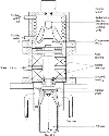
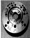
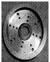
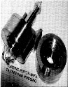
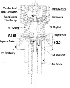
The vertically oriented turboexpander rotor [Fig. 1] has a turbine and the brake wheel at its two ends. The shaft consists of a collar, which together with the thrust bearings on its either side, forms the axial bearing system. Improvements have been made, over a period of time, in the thrust bearing design and configuration to enable a jump in the stable operating speed of the rotor from 3.3 kHz [3] to 4.2 kHz [4] and now to 4.5 kHz (theoretical design speed). The present design incorporates a top thrust bearing of tilting pad type [Fig. 2] while the bottom one is helical grooved [Fig. 3], Damping, in the form of silicon rubber, is provided around the pad pivot. This combination of bearing has emerged to be the best during our laboratory trials, being particularly successful in passing over critical speeds, owing to the conformability and tilting action of the pads and good load bearing characteristics of the grooves. The journal bearing system constitutes of the shaft and a pair of tilting pad bearings [Fig. 4] designed to align the rotor and take up any load due to unbalance. The weight of the rotor is taken up by a passive magnetic bearing consisting of repelling magnets lodged in shaft and housing [Fig. 1], This system also aids in smooth take off and landing of the rotor. |
Top ROTOR BEARING SYSTEM-MAJOR SPECIFICATIONS Thrust Bearing Clearance (End Float): 70 to 150 microns (varies from unit to unit). Pad material: AISI 4140 Steel. Journal Bearing Diametral Clearance: 75 to 100 microns (varies from unit to unit). Pad material: Graphite impregnated with Babbit alloy. Rotor Unbalance: less than 6 mg at 8mm radius, both at the turbine as well as the brake compressor ends. Rotor Bearing Run out: 10 microns or less is tolerated on the thrust bearing face. The shaft cylindricity and runout of the collar (thrust bearing face) is of the order of 2 microns. Shaft Material: K Monel 500. Magnetic Bearing Magnetic material: Sumerium Cobalt. Field strength: 1.65 KGauss on flange and 0.5 KGauss on rotor (for a rotor lift of 350–400 microns). Clearance between turbine and diffuser 200 to 300 microns (varies from unit to unit). Top TURBOEXPANDER HOUSING DESIGN AND ASSEMBLY ISSUES Fig. 5 shows a sectional view of a typical cryogenic turboexpander housing. The major design and assembly issues for the system are discussed below. |
Tolerance build up effects are taken care off through spacers. These spacers are used to control the total thrust bearing clearance (axial end float), axial clearance between the turbine impeller and diffuser as well as the clearance between the brake compressor and its inducer. The assembly is based on axial sealing using O-rings. Cold leakage is prevented by use of hollow and thin members at the cold end, Teflon® cylinder and labyrinth seal. High quality fabrication and runout of the order of 10 microns is required for proper alignment. Permanent joint (welding) is used at the cold end.
Top ROTORDYNAMIC EVALUATION OF THE TURBOEXPANDERS Several rotors are assembled and rigorous rotordynamic trials conducted at CrTD laboratory to gauge the dynamic characteristics of the unit. The parameters of significance for these tests are the vibration signature and the starting/takeoff pressure at each successive runs. The rotors tested have survived more than 20 start-stops without any significant change in starting pressure (1.5 bar gage at HP turbine inlet) and vibration signature. |
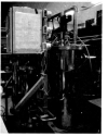
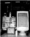
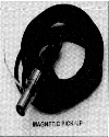
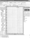
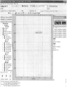
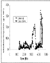
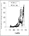
The Experimental Rig The rotordynamic test rig consists of a small cold box with the turboexpander unit mounted on top of it [Fig. 6]. Helium gas is fed to the system from a screw compressor (13 bar HP to 1 bar LP) with a maximum delivery of 2 NM3/min. The Vibration Analyzer System The instrumentation involves Industrial ICP® accelerometers, make IMI, model M621B40 (weight: 2.8 g, range 1.6 to 30000 Hz, sensitivity: 10mV/g, resonant frequency: 85kHz) mounted on the turboexpanders and signals fed to an OROS® vibration analyzer system [Fig. 7] with real time Fast Fourier Transform (FFT) capabilities using OROS® NVGate® software. It is possible to record the vibration signatures and play back for post analysis. The rotor speed sensing system The rotor speed is sensed through a magnetic type speed pickup [Fig. 8] and a magnetic target fixed to the shaft and located in between the two journal bearings. This target is shrink fitted in a diametral hole drilled through the non magnetic shaft. The speed pick up tracks the rate of change of magnetic flux linkage above a threshold limit and twice per shaft revolution. At any given rotor speed, the FFT shows all the components of vibration, synchronous, sub-synchronous as well as super synchronous. Snapshots from the FFT response at highest operating speeds of 2,70,070 RPM for two different assembled rotors “tx-ns-01” and “tx-ns-02” are shown on Fig.s 9 and 10 respectively. Synchronous vibration response in terms of ‘g’-the acceleration due to gravity for the full range of speeds right from start-up and up to the maximum operating limit for the two turboexpander rotors “tx-ns-01” and “tx-ns-02” are shown in Fig.s 11 and 12. Both the coast-up and coast-down responses are represented in the same graph. Top OBSERVATIONS AND DISCUSSIONS It is clear from Fig.s 9 and 10 that the vibration levels at the maximum operating speed of 4.5 kHz is very low, 0.18 g and 0.22 g respectively. The same is true for all other rotors tested in the laboratory. All along, during the coasting up (and also during coasting down), no evidence of any half speed whirl is seen. Even the snapshot does not show any significant half speed vibration component. This concludes that the current design of rotor bearing system is stable for the range of operation of our interest. |
The synchronous vibration plots of Fig.s 11 and 12, throws light on some other aspects of the rotordynamic system. It is very much conclusive from the curves, especially during coast-up, that a system critical speed is present in the vicinity of 4 kHz. The critical speed is also seen to be split. The bearing x-y asymmetry, due to 3 tilting pads being arranged symmetrically in 360°, may be the cause of this split. |
It is also observed that the peak vibration response varies slightly from unit to unit. It is not possible to replicate the exact journal bearing clearance on all units and hence, the bearing radial stiffness, which is a strong function of this clearance, varies from unit to unit. The critical speed, in turn, shows slight variation too. The damping available in the current design is sufficient for all the rotors to pass through the critical speed to maximum operating speed. However, future higher efficiency turboexpanders with smaller gaps between turbine and diffuser might require smaller bearing clearance backed up by more effective radial damping to pass through critical speeds without any glitch. To achieve those tight clearances, a much higher quality of machining is required though. |
Top Figures | Fig. 1.: Schematic of a typical cryogenic turboexpander
|  | |
| | Fig. 2: Tilting Pad Top Thrust Bearing
|  | |
| | Fig. 3.: Helical Grooved Bottom Thrust Bearing.
|  | |
| | Fig. 4.: Tilting Pad Journal Bearing.
|  | |
| | Fig. 5.: Sectional view of a typical cryogenic turboexpander housing.
|  | |
| | Fig. 6.: Laboratory Experimental Rig.
|  | |
| | Fig. 7.: OROS® Vibration Analyzer System
|  | |
| | Fig. 8.: Magnetic type speed pick-up
|  | |
| | Fig. 9.: FFT snapshot of “tx-ns-01” at maximum operating speed of 2,70,070 RPM.
|  | |
| | Fig. 10.: FFT snapshot of “tx-ns-02” at maximum operating speed of 2,70,070 RPM.
|  | |
| | Fig. 11.: Synchronous Vibration Response Plot for “tx-ns-01”.
|  | |
| | Fig. 12.: Synchronous Vibration Response Plot for “tx-ns-02”.
|  | |
|
|