Development and study of an indigenous helium purifier based on low temperature high pressure adsorption of impurities Maiti Trijit K.1, Dey Ranadhir2, Sahoo R. K.3, Sarangi Sunil K.4 1VECC/DAE, Kolkata 2VECC/DAE, Kolkata 3NIT, Rourkela 4NIT, Rourkela Abstract In collaboration with VECC, Kolkata, NIT, Rourkela has taken up the project of the development of cryosorption based helium purifier. The helium purifier has been designed for purifying helium containing 40% air impurities to a contaminant level below 50 ppm at a flow rate of 20Nm3/hr and operating pressure of 120 bar(g). Low pressure impure gas is recovered in gas bag from experimental set up. It is compressed, then purified by a shell & tube heat exchanger, a tube-in-tube heat exchanger, a subcooler, a liquid air separator and five LN2 cooled activated charcoal adsorber columns in series. Purity monitoring, regeneration system and gas storage manifold have been provided. All the major components have been fabricated, assembled and commissioned at NIT, Rourkela. It has been successfully tested with low percentage of impurities and detailed testing is underway. Top Keywords Activated charcoal, Cryosorption, Grade 4.5 helium. Top |
INTRODUCTION The largest application of pure helium is in cooling superconducting magnets, key to high energy accelerators, superconducting cyclotron and Magnetic Resonance Imaging (MRI) scanners. In any cryogenic installation where helium liquefier is running in closed cycle to maintain liquid helium level of cryostat, housing superconducting magnet, helium purifier is an indispensable device to conserve helium gas, to reduce the cost of liquid helium to the users and to ensure adequate supply of liquid helium for research activities. At present, Indian academic institutions and research centers import helium purifier which is not only very expensive in terms of foreign exchange, but also a time consuming affair. And we are to depend on foreign nations for its spares. So, National Institute of Technology, Rourkela, took up the project of the development of cryosorption based helium purifier in collaboration with Variable Energy Cyclotron Centre, Kolkata, which primarily aims at developing helium purifier indigenously. |
Top PROCESS DESIGN OF HELIUM PURIFIER VECC, Kolkata has been working with the cryosorption purification system for long time and have successfully experimented with three numbers of activated charcoal columns to obtain Grade 4.5 helium from 99% pure helium at 25 bar(g). This model has been working as pre-purifier to the existing imported purifier of VECC, Kolkata to enhance the productivity. This performance of pre-purifier is encouraging for developing an enhanced version of the same. The brief technical specification of the helium purifier project is hereunder. |
Operating Pressure of purifier & Temperature: 120 bar (g) & 77 K |
Input helium purity: 60% i.e. 40% air impurities (max.) |
Output helium purity: 99.995% i.e. Grade 4.5 Run time for purification: 6 hours Adsorbent: Coconut shell granular activated charcoal |
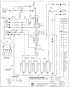
P&l Diagram of the helium purifier is presented in Fig. 1. |
The basic principles involved in helium purification process are condensation of air impurities at heat exchangers and cryosorption of remaining impurities at activated charcoal columns. The purifier system has been designed to purify 60% pure helium to 99.995% purity. Gas bag collects impure helium from high pressure cylinders or any cryogenic experimental set up, and acts as low pressure buffer for compressor inlet. Compressor compresses this impure helium to 120 bar(g) at a flow rate of 20 Nm3/hr. The gas then passes through an oil and water separator vessel, three numbers of heat exchangers and liquid air separator vessel in sequence. The first heat exchanger acts as moisture dryer which brings down pressure dew point to 1°C, the second and the third one condense air impurities and reduces it to 0.83%. Liquid air separator vessel, then collects this condensed air which is purged at regular intervals depending on the impurities level. Now, helium, containing only 0.83% air impurities, enters the adsorber columns which reduces air impurities to less than 50 ppm and thus yields Grade 4.5 helium. The third heat exchanger, liquid air separator and adsorber columns are totally submerged in LN2. Back pressure regulator at the outlet maintains the constant operating pressure of 120 bar(g) at adsorber columns. The purifier works in two phases-Purification and Regeneration. |
The principal components of the purifier system are as follows: |
1) Gas Bag 2) Compressor 3) Oil and Moisture Separator Vessel 4) Shell & Tube Heat Exchanger 5) Tube-in-tube Heat Exchanger 6) Coiled Tube Heat Exchanger or Subcooler 7) Liquid Air Separator Vessel 8) Snow Filter 9) Adsorber Columns 10) Tubular Heaters 11) Superinsulated LN2 vessel, housing all internal components, viz. tube-intube heat exchanger, subcooler, liquid air separator vessel, snow filter, adsorber columns and tubular heaters 12) Back Pressure Regulator 13) Pure and Impure Helium Cylinder Manifold 14) Pipe layout consisting of tubes and valves 15) Instrumentation. |
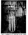
Top DEVELOPMENT OF COMPONENTS Gas Bag Presently, liquid helium user establishments in India import helium gas bags, which are very expensive. Hence, we collaborated with Softex Industrial Products Pvt. Ltd, Kolkata to design and develop the same. This gas bag of 5 cu. m volume has dimension of 3 m × 2.5 m in deflated condition and weight of 18 Kg. Its maximum operating pressure is 50 mbar(g) and has an oil based safety relief valve of 55 mbar(g) set pressure. The gas bag material is four layered textile reinforced rubber viz. chlorosulphonated polyethylene rubber, polyamide cloth, polychloroprene rubber and polyester cloth, and is 1mm thick. One number nozzle of 25 mm diameter has been provided for process connection. Nozzle consists of two numbers of injection molded Class 150 teflon flanges with neoprene washers to provide leak tightness. Gas bag has been tested by dry air at 200 mbar(g) for 79 hours. The pressure drop is 2.5 mbar in 79 hours which is quite negligible. Encouraged by this success, VECC, Kolkata has purchased two numbers of similar type gas bags of 20 m3 capacity for Superconducting Cyclotron which are working satisfactorily. Compressor and other components Compressor is necessary for creating high pressure to ensure efficient condensation and adsorption of impurities and hence, we obtain better adsorption isotherm. We selected Metec Corporation, South Korea, whose model tallied our specification and its price is about three times cheaper than the European product. Oil and Moisture Separator Vessel is used for separating moisture from high pressure impure helium and Liquid Air Separator Vessel for separating oxygen and nitrogen droplets and mists from impure helium stream and these works on the principle of vertical cyclone separator. Design calculation of liquid air separator, based on settling velocity, reentrainment and liquid hold-up time of 15 min, shows that vessel inner diameter and minimum height are 97.18 mm and 580 mm respectively, and inlet diameter is 8 mm. In Shell and Tube heat exchanger, Shell is fabricated out of 50NB Sch80 SS 304 pipe and inside helical coil of 6mm Outer Diameter (OD) tube. Tube-in-tube heat exchanger consists of two concentric tubes coiled helically which involves counterflow fluid movement. This has been fabricated from 16 mm and 10 mm OD seamless SS316L tubes. Subcooler is single helical coil design with tube OD of 10 mm and coil diameter of 580 mm. Adsorber Columns The adsorbents commonly available in Indian market are Activated Alumina, Molecular Sieve, Silica Gel and Activated Charcoal. Nitrogen adsorption efficiency of coconut shell activated charcoal is better than any other adsorbents at 77K. As India is one of the major producers of coconut shell charcoal, hence it has been chosen in preference to other adsorbents. The activated charcoal used for this work has been purchased from Exal Corporation, Vadodara, Gujarat. The physical properties are as follows: Grade: AC 4/8 Sieve size:-4 + 8 BSS BET surface area, m2/gm, (min): 1600 Adsorption capacity in terms of Iodine number (min), mg/gm: 608 Moisture, percent by mass (min): 4.5 Apparent density, gm/cc: 0.55 Theoretical calculation reveals that after heat exchangers and liquid air separator, impure helium is saturated with 0.83 % air which will have to be adsorbed by activated charcoal. As per BET (Brunauer, Emmett, Teller, 1938) equation, relationship followed for multi-layered adsorption, total charcoal requirement is 10.50 Kg. Adsorber column dimension has been determined based on approach velocity of gas and pressure within the column. The pipe selected is 50NB Sch80 ASTM A312 TP304L, in which gas velocity is 0.02 meter/sec which is well within optimum range. Few layers of 40 mesh wire cloth and molecular sieve layer of 75 mm thickness has been used at adsorber column ends which acts as filter to charcoal dust. Purifier system has five numbers of U-shaped vertical stainless steel adsorber columns, connected in series by 6 mm OD tubes and each column length is 2.3 m. A plug of 15mm OD is welded at the bottom of each column for charcoal replacement. The calculated total pressure drop in five numbers of adsorber columns is 90 mbar by using Ergun theory, which is negligible. Regeneration System Thermal swing regeneration technique has been adopted for purifier system. In this process, adsorber columns are heated to 120° C by six numbers of 1 KW tubular heaters for 4 hours for desorption of gases and then evacuated with a rotary pump for last 2 hours up to the pressure of 10−3 mbar. Temperature is monitored by Pt100 RTDs placed on the bottom face of top flange and adsorber column body. The system is then purged with Grade 4.5 helium by reverse flow and system is ready for the next run. Top ASSEMBLY OF PURIFIER SYSTEM Superinsulated LN2 vessel has been designed in such a way that all internal components of purifier consume minimum LN2 for cooldown. Its inner diameter and inner height are 600 mm and 1600 mm respectively. A bolted top flange plate seals the vessel with an O-ring. The internal components of purifier unit have been placed in a cage, which is suspended from top flange. All electrical feedthroughs for heaters and temperature sensors pass through this flange. The valve panel is fixed on the top flange. All the process connections were made through the top flange and connected to external valve panel. LN2 level is monitored by level gauge, consisting of three numbers of Pt100 RTDs fixed to a tube, which is held by Wilson coupling on top flange. After completion of assembly, pneumatic leak test was performed with nitrogen gas at test pressure of 165 bar(g) in accordance with ASME B 31.3. |
Top RESULTS AND DISCUSSION In the experimental set up, impure helium has been prepared in gas bag, by addition of dry nitrogen to pure helium by passing through rotameter. Now, we are in the process of conducting experiments to plot the breakthrough curves, with nitrogen impurities ranging from zero to 40%. We have already tested the purifier operation for few hours, by 1% and 2% dry nitrogen impurity, and obtained 99.995% helium at the output side which has been monitored by Linde MultiComponent Detector, Type WE 37M-3. |
Top ACKNOWLEDGEMENT Funding of the project by Board of Research in Nuclear Sciences, Mumbai, vide BRNS sanction number 2006/34/02/BRNS with ATC, is gratefully acknowledged. The authors are thankful to Cryogenic Concern Pvt. Ltd., Kolkata, for their valuable help in the fabrication, assembly and commissioning. |
Top Figures | Fig. 1:: P & I Diagram of Helium Purifier
|  | |
| | Fig.2:: Assembly of internal components
|  | |
|
|