
|
|
|
(13.58.182.29)
|
|
Users online: 13736
|
|

|
|
|
|
|
Ijournet
|
|
|
|
|
|
|
Design and development of HTS Magnet insert to produce 12 T of magnetic field Pradhan J.1, Bhunia U.1, Naser Z.A. Md.1, Roy A.1, Thakur S.K.1, Bhattacharyya T.K.1, De A.1, Bandyopadhyay S.1, Panda U.1, Das M.1, Mallik C.1, Saha S.1 1Variable Energy Cyclotron Center, 1/AF Bidhannagar, Kolkata, 700 064 Abstract High Temperature Superconductor (HTS) magnet insert is designed and developed. This will be placed at the central bore of Low Temperature Superconducting (LTS) solenoid magnet operating at liquid helium bath. The combined magnet system produces about 12 Tesla of field at 60mm bore diameter. This will be used for different material testing, characterizations and also to develop state of the art HTS coil technology, aimed specifically for magnet for energy storage and beam line. This paper describes overview of the design and other critical aspect of the of the magnet system Top | INTRODUCTION The critical properties of High Temperature Superconductor (HTS) have been improved considerably and several HTS based magnet system have been designed and fabricated worldwide. HTS offers advantages over Low temperature Superconductor (LTS) at high magnetic field. Recently, VECC has taken up an initiative for the research and development programme on HTS based activities, like coil, current lead etc. About 2Km of high strength HTS tapes was purchased from M/s Sumitomo, Japan. (It's critical properties are shown in Table 1). As a part of development programme a HTS magnet insert of 60mm bore diameter has been designed initially. This will be placed inside the LTS magnet bore of 120mm diameter of 0.6MJ SMES system [1], This combined magnet system produces about 12T of magnetic field, which can be used for high field physics experiments. The objective of the programme is to develop state of the art HTS coil technology. This will be later integrated with 4K cryo-cooler, and will produce about 6T field. This complete 4K cryo-cooler based cryogenic test set-up will provide variable fields and variable temperatures for sample characterization, sensor calibration and other research programmes. In this paper both electromagnetic and mechanical design features of the HTS magnet insert has been described. Other design issues are also overviewed. |
Top Design of magnet insert It is always desirable to minimize the length of the HTS tape for a given field considering the critical characteristics of HTS tape, coil stress and protection against quench. To produce a large magnetic field, it is necessary to have large current density. Due to the anisotropic nature of the HTS material, its critical current is much lower when the magnetic field is applied normal to its surface than when it is parallel to its flat surface. So the critical current of a coil primarily depends on the value of radial magnetic field in the coil winding section. The magnetic fields of the solenoid coil have significant radial components at the coil ends. Therefore the size and shape of the magnet requires to be optimized to reduce the radial magnetic field. This problem has infinite solutions and some initial constraints were considered to reach a feasible solution. Some of these constraints arise from the coil geometries and others are due to technological reasons. |
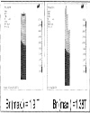
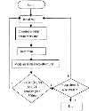
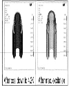
Generally, the cross-sectional shape of the super-conducting coil is rectangular but that of the proposed HTS magnet insert is stepshaped, consisting of co-axial section coils with different lengths. This reduces both the radial component of magnetic field and the winding length of HTS tape for a given central field (∼12T). The comparison shown in Fig. 1 shows the radial component reduction due to step-shaped coil as compared to rectangular coil for the same length of the conductor to get the central magnetic field of 12T in both cases. We have used finite element based software ANSYS™ for magnetic field calculation. Its in-built optimization routine based on sub-problem approximation was used to get the optimum geometry of the HTS insert coil. The objective function is to minimize the radial magnetic field at the coil ends. Nine design variables, which determine the shape of each section of the step coils, were used along with different constraints as state variables for optimization. The critical bending diameter of the HTS tape and inner diameter of the LTS coil acts as lower and upper limit respectively. The coil current density Jopwas obtained from the pre-defined operating current. This operating current was determined by short sample value of the HTS tape scaled with safety margin of 20%. The optimization strategy aims to minimize the conductor length (or volume), which basically optimizes the magnet cost. Fig. 2 shows the flow chart of optimization used for HTS magnet insert. The value of radial magnetic field at coil ends of the proposed step-shaped configuration is smaller and is about 70% of the optimized rectangular shaped coil. |
In the stage of magnet design, stress distribution inside the coil at different conditions must be considered, as it is necessary to know the limiting values of loading, bending and twisting to avoid degradation of critical current when handling HTS tape. It is also a known fact that mechanical motion of the superconductor is one of the causes of degradation and quenching of superconducting coils. This is created by the radially outward Lorentz force, which interacts with the stress, resulting from the preceding pre-stress, if any, and thermal stress due to cool-down. The thermal contraction during cool-down, produces compressive stress for materials generally used in the coil. |
To prevent any such mechanical motion the conductor must either be subjected to compressive radial stress or should be potted with suitable epoxy resins. The limits for the hoop stress and the axial stress induced by Lorentz forces are determined by the critical tensile strength of the HTS tape at low temperature and the critical current degradation. The maximum allowable stress is 150 Mpa in the design, which has no evident of the critical current degradation of the Bi-2223 tape [2]. We have studied both cases of potted conductor and pre-stress conductors without potting to calculate the stress distribution during cool-down and after maximum excitation. Experimental studies are being carried out to obtain critical current degradation, if any, due to externally applied tension. Stress distribution inside the coil is calculated both analytically and using finite element software ANSYS™ and found out to be similar as shown in Fig. 3. It is found that about 40Mpa of pre-tension is necessary to ensure compressive stress at all conditions with the maximum hoop stress being about 70Mpa at the coil outer radii as depicted in Fig. 4. This hoop stress is within the critical tensile strength, of HTS tape. We have analyzed stress distribution when the coil is potted with epoxy resin and the Von Mises stress distribution within the coil is shown in Fig. 5. with a maximum value of 10Mpa. |
Studies were carried out to calculate magnetically coupled interaction force between HTS magnet insert and outer LTS coil. When a magnetic field center of the two coil systems does not coincide, a magnetic interaction force appears. As a result of the off-centre, an attractive force fz, in the axial direction, as a stable equilibrium, and a repulsive force fr, in the radial direction as a unstable equilibrium is produced. The supporting structures of the HTS magnet insert absorb this interaction force. When a magnetic field center of a HTS insert is shifted by 1mm, it experiences fz= 17 kgf/mm or Fr= 20kgf/mm respectively. |
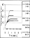
A computer code was developed for analysis of the transition process of HTS coil to normal state based on finite difference method. Due to the dependence of the material properties on the temperature an exact formulation of the problem produces non-linear differential equations, which can only be solved numerically. We have not considered cooling by helium bath and also quench back is not modeled to simulate the worst conditions during quenching of magnet. Maximum hot spot temperature is calculated and shown in Fig. 6 for different values of dump resistance and voltage detection threshold. |
It is generally acceptable to keep the maximum temperature within 150 K and so dump resistance of 300mohm is acceptable with detection threshold of 50mV. Itis observed that a passive protection scheme will not be possible and protection should have external dump resistance. Studies were also carried out to account for possible scenarios that may eventually occur after the quench like rise of cryostat pressure, voltage rise and helium boil-off rate. |
Top Conclusion The detailed design studies were carried out for the development of HTS magnet insert and HTS coil as a whole. We have made different provisions open keeping in mind the future development of conduction cooled HTS magnet using the same HTS tapes. We are carrying out different measurements to ensure the optimum performance of HTS tape |
Top Figures | Fig. 1: Cross-sectional shape of HTS insert showing reduction of radial component of magnetic field at the coil ends by using stepshape coil (RHS)
|  | |
| | Fig. 2: Flow chart of optimization
|  | |
| | Fig. 3: Radial stress distributions Analytical (k) & ANSYS (−)
| 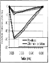 | |
| | Fig. 4: Radial and hoop stress distributions (for 40Mpa winding tension)
| 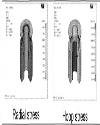 | |
| | Fig. 5: Von Mises stress distributions when the coil is potted
|  | |
| | Fig. 6: Maximum temperature rise for different combination of dump resistance and detection threshold voltage
|  | |
|
Table Table 1:
| | Critical current @77K, SF | >150 A | | n-value | ∼ 17 | | Width | 4.6 mm | | Thickness | 0.4 mm | | HTS material | BSCCO-2223 | | Lamination material | Copper alloy | | Max. Single length | 500mts | | Critical wire tension (RT) | 280 N (28kgf) | | Critical tensile strength (@77K) | 250 Mpa | | Critical double bend diameter (RT) | 60 mm |
| |
| | |
|
|
|
|
║ Site map
║
Privacy Policy ║ Copyright ║ Terms & Conditions ║

|
|
|
751,552,904 visitor(s) since 30th May, 2005.
|
|
All rights reserved. Site designed and maintained by DIVA ENTERPRISES PVT. LTD..
|
|
Note: Please use Internet Explorer (6.0 or above). Some functionalities may not work in other browsers.
|