Optimization for solenoid-type superconducting magnetic energy storage coil Bhunia U1, Pradhan J1, Saha S1, Mallik C1, Bhandari R K1 1Variable Energy Cyclotron Centre, Department of Atomic Energy, 1/AF, Bidhan Nagar, Kolkata-700 064, India Abstract The operating cost of superconducting magnetic energy storage (SMES) system highly depends on the ac loss due to magnetic field transients and heat in-leak to the system. Therefore, reduction of ac loss and coil or cryostat surface area since it reduces heat inleak into the system is an important design criteria for superconducting magnetic energy storage system. This paper presents a new and elegant optimization approach of finding geometrical parameters of a solenoid type superconducting magnetic energy storage coil that minimizes both ac loss as well as coil surface area for a given allowed hoop stress and stored energy. A fundamental prerequisite of the design is that if the initial design constraints such as stored energy and allowable circumferential or hoop stress in the winding are fixed and critical characteristics Jc(B) of the superconducting cable are given, the optimization technique using Differential Evolution (DE) method provides unique solution of design parameters and operating condition. For a given critical characteristics of the cable, dependence of optimized geometrical and operating point (Bm, l) in various stored energy levels has been investigated. Effect of allowed hoop stress on optimized parameters has also been investigated. Top Keywords SMES, Superconducting Magnet, AC Loss. Top |
INTRODUCTION Superconducting magnetic energy storage (SMES) system has the ability to mitigate short time voltage fluctuation and sag effectively. Variable Energy Cyclotron Center has taken up research and development program to built SMES system for its accelerator facility. This will drastically reduce the downtime of the facility due to unexpected power fluctuation, sag, etc. Optimization of superconducting solenoids has been studied for past few decades [1-5]. The published works were mostly dealing with the relationship between geometrical parameters of coil and magnetic field. Unlike previous works, this paper gives an analytical description of the optimization problem in terms of coil parameters and aims to minimize both ac loss and radiation heat in leak since in present scenario, price of Nb-Ti based superconductor has reduced considerably and it hardly preset the total cost of SMES device. In general, the SMES system is operated in DC energy storage mode. But, if energy is charged or discharged, the current and magnetic field are changed. A time varying magnetic field causes dynamic loss especially the ac loss in the stabilizer, superconducting cable, all metallic parts, etc. |
Therefore, the design goal of SMES coil is to minimize ac loss to reduce the dynamic heat load to the cryogenic refrigeration and coil or cryostat surface area to reduce static heat load into the cryostat since both the parameters have a direct impact on operating cost of the device. In this study, we have considered the solenoidal type of SMES coil since it has the advantage of high energy storage density and simplest configuration. The paper presents multi-variable non-linear constrained global optimisation using Differential Evolution (DE) method of geometrical and operating parameters (Bm, I) to be met for a given stored energy level and power rating, maximum allowable circumference or hoop stress of the coil, and maximum allowable discharge voltage across the SMES coil. The corresponding optimal design of 5MJ, 0.5 MW SMES coil using Rutherford cable and comparative analysis is given. |
Top MATHEMATICAL FORMULATION The geometry of a solenoid is completely defined by its inside radius (a), shape factor ratio α = b/a, and β = l/a with outside radius(b) and total length of 21 as shown in Fig 1. |
The inductance (L) of the air core solenoid coil given by |
Where, N is the total number of turns of the solenoid; 0{α,β) is a geometry dependent factor given by Welsby [8] as permeability in free space. |
The energy stored in a solenoid type winding is given by Wesche4 |
Peak field to center field ratio is defined as, |
The winding volume is given by, |
The center field B0 and peak field Bm of the solenoid can be written as |
Here K(α,β) is given [9] as |
Here, higher order correction terms K2, K4, and K6 are as given by Feng6 as |
Basic work in designing any superconducting coil is to get characteristics of the wire such as critical current density (Jc) vs external magnetic field (B). Considering the space or filling factor(λ) of the coil, the safety factor (ζ), from the short sample critical characteristics of the superconducting cable (i.e.jcvs B), average overall or operating current density (J) is determined in terms of coil peak field (Bm) as follows: |
Usually safety factor ζ is kept roughly around 30 %, while space factor (λ) depends on winding details such as insulation thickness, etc. Once the superconducting cable along with its insulation and winding scheme is fixed, space factor can be determined. For our study with Rutherford cable as specified in Table. 1 and interlayer spacer for liquid helium passage, space factor is determined to be around of 0.85. |
The variation of overall current density with magnetic field can be fitted in terms of J-B/J by analytical expression as |
Here, p and q are the parameters fitted from J vs Bn/J plot. Substituting from equation (8), current density can be expressed as, |
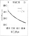
For example, Nb-Ti alloy based Rutherford cable as specified in Table.1 has engineering current density Jat 4.2 K as shown in Fig 2. The current density (J) can be fitted in the form of equation (11) with fitting parameters as, p =7.6322 and q = 1.42619x1(T8 |
For solenoid type coil, maximum stress occurs in the median plane (z=0) of inner layer of the winding. Regarding coil as composite conductor/insulation structure, hoop stress developed at the median plane of inner layer of winding (i.e. r = a & z = 0) of an isotropic solenoidal coil as given by Wilson [7] is, |
Figure 2. Critical characteristics of the superconducting wire |
Axial magnetic field outside a finite size solenoid in its median plane (z=0) can be approximated [8] as |
While designing a SMES coil of a given rating, it is extremely important that the voltage developed across the coil leads is kept within safe value so that no electrical discharge, damage in insulation, etc. occurs. |
Optimization for Solenoid-type Superconducting Magnetic Energy Storage Coil |
Voltage developed across the leads at time Instant t=0 of discharge can be written as, |
If t is the carry over period and n (=0.9) is the efficiency of SMES coil, maximum voltage developed towards the end of carry over period can be written as, |
Where Ac is conductor cross-section and T is decay period of current corresponding to rated power of SMES coil. |
Top OPTIMIZATION METHODOLOGY The design goal is to minimize the dynamic loss in the superconductor winding and steady state loss into the cryostat. |
Dynamic Heat Load Rutherford cable in solenoid type winding of SMES coil mainly experiences parallel magnetic field to the cable broad surface since the radial field component in the winding space for the solenoid is very less w.r.t. axial field. Time transient of magnetic field contributes ac loss dissipation mainly originated from superconducting strands and cable: i) Hysteresis loss in the superconducting filaments caused by the induced persistent current in the filament. Hysteresis power dissipation (pf) in the winding (pf) is given by, Where: df and λsc is filament diameter and fractions of superconductor in a filament respectively. ii) Coupling power dissipation (pcf) per unit volume originated by electromagnetic coupling among filaments in the strand throuqh the matrix is given by, Where lp is filament twist pitch, ρt is effective transverse resistivity across the matrix, and λwire is the fractions of filaments in a strand, ii) Coupling power dissipation (pcs) per unit volume among strands in the Rutherford cable for magnetic field parallel to the broad surface of cable is given by, Where: Ra is adjacent resistance per cross over of strand; c and d are half width and halfthickness respectively of the cable; λcabie is the fractions of superconducting strands in cable in the winding cross-sections; lt is half the braid transposition length in the cable. Total power dissipation due to AC loss would be: Since the magnetic field over the winding space varies, weighted average of magnetic field is calculated and to be replaced in equation (16).Considering the linear fall off of magnetic field along the radial direction in winding, which is fairly good approximation, axial field B(r, z) can be expressed as On substituting B(r, z), equation (19) can be written as, where Static Heat Load It is very important to reduce the surface area of the SMES coil in order to achieve small static heat load. For ten layers of multi-layer insulation around the coil chamber, heat dissipation to liquid helium chamber from 77 K shield in a vacuum level of 10−6 mbar range would be ∼qr =0.03 WI Sq.m [9], Therefore, static heat load due to radiation and gas conduction is given as Another significant static heat load comes from the vapour-cooled current lead of the coil. Considering standard heat load of qlead-0.002 W/A from optimised current leads, contribution of heat load from a single pair of current leads may be written as: Where, Ac is conductor cross-sectional area. Therefore, total static heat dissipation neglecting the conduction heat load would be The Objective Function Total dissipation in the SMES coil is the objective function and therefore the problem can be written as Minimize Subject to constraints: Here, σa and Va are the allowable hoop stress and voltage across terminals respectively. This is a multivariable nonlinear constrained global optimisation problem. Differential Evolution (DE) method, which is population based global optimisation algorithms and relatively robust, is used to find out the global minima. Top Result and Discussion Based on the foregoing iterative DE optimisation algorithm, Table 2 shows the results of three groups of 5 MJ capacity. |
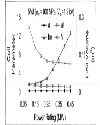
The optimal design study for a 5 MJ system using Rutherford type cable as specified earlier has been carried out as an example. The dynamic and steady state loss for a given stored energy of SMES coil with constraint of maximum allowable voltage across the coil terminals and hoop stress in the inner layers is as shown in Fig. 3. It is observed that higher the power rating, both the loss term increases. |
The corresponding optimized coil parameters (a, α, β) are as shown in Fig. 4. It is interesting to note that the optimised coil diameter and conductor volume decreases with increasing power rating for a given stored energy of the coil. |
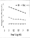
It is also quiet expected to observe that the peak magnetic field in the coil decreases with increase power rating of the coil as evident from Fig. 5 since this reduces the dynamic loss. |
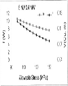
Effect of allowable hoop stress on the coil design is very important and higher the allowable hoop stress reduces the conductor volume and overall losses as shown in Fig. 6. |
Throughout this process of optimisation, maximum allowed voltage across the coil terminals is assumed to be 1.2 kV, which is safe enough against any insulation breakdown or discharge. In fact, SMES coil of higher stored energy level and rating are made to operate at higher allowed voltages, and hoop stresses. These two criteria again reduce the total loss as well as coil volume. The mathematical formulation of the problem is completely analytical and provides optimized solution that minimizes both the static heat load in to the cryostat and dynamic heat load due to ac loss during the magnetic field transients. It is also important to note that both the losses decrease with higher allowable hoop stress in winding. Even though sufficient safety margin of 30 % has been incorporated in determining engineering current density, extensive quench calculation needs to be done in order to finalize the coil protection scheme from any thermal instability. The optimization methodology described is used to design a 5 MJ SMES coil for the first phase of SMES program in our centre. In the process of optimization, ac loss due to axial field transients is only considered since the loss contribution due to radial field distribution is significantly lower w.r.t. axial field. Though, we have considered here Rutherford type cable, however, other type superconducting cable can also be considered and above methodology can be utilized. |
Top Figures | Figure 1.: Schematic of coil
|  | |
| | Figure 2: Critical characteristics of the superconducting wire
|  | |
| | Figure 3.: Optimised loss for various power ratings.
|  | |
| | Figure 4.: Coil parameters with power ratings
|  | |
| | Figure 5.: Variation of peak field with power rating.
|  | |
| | Figure 6.: Coil volume & Loss with allowable hoop stress.
|  | |
|
Tables | Tablel.: Cable considered for study.
| | Type | Rutherford | | Material | Nb-Ti alloy | | Dimension (mm) | 5.5x2.06 | | Strands | 10 | | Strand diameter (m) | 1.065 | | Filaments in each strand | ∼7000 | | Filament diameter (pm) | 7.7 | | Twist pitch (mm) | 15 | | Transposition Length(mm) | 115 | | Cu:Sc | 1.65 | | Crossing contact resistance (μΩ) | ∼15 | | Ic (at 4.2K, 5T) (A) | ∼9000 |
| | | Table2:: Basic design parameters for E=5 MJ
(σm=100 MPa & Vm=1.2 kV))
| | P | a | α | β | J×106 | f | Bm | | 0.2 | 0.27 | 1.23 | 2.25 | 89.3 | 4.45 | 6.35 | | 0.3 | 0.23 | 1.15 | 4.90 | 134 | 7.32 | 5.72 | | 0.4 | 0.2 | 1.12 | 9.76 | 179 | 10.52 | 5.08 |
| |
|