Effective thermal conductivity of an axial groove cryogenic heat pipe Kumar M. Senthil1, Kumar A. Senthil1 1School of Mechanical and Building SciencesVIT UniversityVellore-632 014, Tamil Nadu Abstract A heat pipe is a device which transports heat at a high rate over considerable distance with a small temperature gradient. When the operating temperature of a heat pipe is less than 123 K, it is known as cryogenic heat pipes, and the working fluid used in the cryogenic heat pipes is any one of the cryogens like nitrogen, oxygen, hydrogen and helium depending on the operating temperature. This paper deals with development and studies of wire mesh wick and trapezoidal axial groove wick heat pipes with nitrogen and oxygen as working fluids. A special liquid nitrogen cryostat has been designed and developed for evaluating the performance of heat pipes. This consists of two main subsystems-a liquid nitrogen cryostat and instrumentation and accessory systems. Many investigators have carried out experiments on the cryogenic heat pipes, in which either the condenser is immersed in the liquid nitrogen or the condenser is connected to cryocooler whose operating temperature can be maintained at constant level by varying the cooling capacity. However, in most of the practical applications, where liquid nitrogen bath is used as the cold reservoir, it is very inconvenient to immerse condenser portion of the heat pipe into liquid nitrogen bath. The present study focus on the performance of trapezoidal axial groove wick heat pipe with the condenser connected to the reservoir externally. The performance of the heat pipe was determined at different temperatures between the triple point and critical temperatures of the working fluid. It is observed that the effective thermal conductivity of the heat pipe is about 2.9 times higher than that of equivalent diameter solid copper rod at about 100 K. Top Keywords Axial groove cryogenic heat pipe, Effective thermal conductivity. Top |
Introduction Of the various devices for transporting heat, the heat pipe is, in many respects the most satisfactory. The principle of the heat pipe was conceived in 1944 by Gaugler and in 1962 by Trefethen (Chi, [1]). However, it was not widely publicised until 1964 when Grover and his colleagues at the Los Alamos Scientific Laboratory independently reinvented the concept. Grover also demonstrated its effectiveness as a highperformance heat transmission device, named it the “Heat pipe,” and developed its applications. Since then over a thousand papers and patents have been published. Among the many outstanding advantages of using the heat pipe as a heat transmission device are: constructional simplicity, exceptional flexibility, accessibility to control and ability to transport heat at high rate over considerable distance with small temperature drop. |
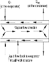
A heat pipe typically consists of a sealed container lined with a wicking material. The container is evacuated and backfilled with just enough liquid to fully saturate the wick. Because heat pipes operate on a closed two phase cycle and only pure liquid and vapour are present within the container, the working fluid will remain at saturation conditions as long as the operating temperature is between the triple point and critical state. As illustrated in Fig. 1 a heat pipe consists of three distinct regions: an evaporator or heat addition region, a condenser or heat rejection region, and an adiabatic region. When heat is added to the evaporator region of the container, the working fluid present in the wicking structure is heated until it vaporizes. The high temperature and corresponding high pressure in this region cause the vapor to flow to the cooler condenser region, where the vapour condenses, giving up its latent heat of vapourisation. Depletion of liquid by evaporation causes the liquid-vapour interface in the evaporator to enter into the wick surface and a capillary pressure are developed there. This capillary pressure pumps the condensed liquid back to the evaporator for re-evaporation. That is the heat pipe can continuously transport the latent heat of vapourisation from the evaporator section to the condenser section without drying out the wick. A detailed theoretical analysis for determining various pressure drops and performance of heat pipes has been presented by Cotter [2]. |
The amount of heat that can be transported as latent heat of vapourisation is usually several orders of magnitude larger than that which can be transported as sensible heat in a conventional convective system. The heat pipe can therefore transport a large amount of heat with a small unit size. |
The temperature drop in a heat pipe is equal to the sum of the temperature drops at the evaporator, vapour flow passage, and condenser. Because of their thin wick structure and the small temperature drop for their vapour flow, heat pipes having thermal characteristics orders of magnitude better than any known solid have been developed |
When the operating temperature of heat pipe is less than 125 K, it is known as cryogenic heat pipes, and the working fluid used in the cryogenic heat pipes is any one of the cryogens like nitrogen, oxygen, hydrogen and helium depend on the operating temperature. |
Many investigators (Armaly [3], Foster, and Murrary [4], Zang 5, Edelstein and Kosson 6) have carried out experiments on the cryogenic heat pipes. In all these investigations either the condenser is immersed in the liquid nitrogen or the condenser is connected to cryocooler whose operating temperature can be maintained at constant level by varying the cooling capacity. However, in most of the practical applications, where liquid nitrogen bath is used as cold reservoir, it is very inconvenient to immerse the heat pipe into liquid nitrogen bath. In that situation, the condenser has to be connected to the cold reservoir externally. In such cases the performance of the heat pipe is expected to deteriorate as the operating temperature tends to increase. The present study focus on the performance of a trapezoidal axial grooved heat pipe with the condenser connected to the reservoir externally. |
Top Experimental Investigations A special liquid nitrogen cryostat has been designed and developed for testing of heat pipes. The wick structure heat pipe with oxygen and trapezoidal heat pipe with nitrogen and oxygen as working fluids were tested at horizontal position with different heat loads. In order to compare the effectiveness of the heat pipe, an experiment was performed on the heat pipe without the working fluid. Moreover in order to get the relative performance of the heat pipe compared to copper rod experiments were also conducted on an equivalent diameter solid copper rod. The idea behind conducting experiments with solid copper rod instead of theoretically calculating its performance is to nullify the effect of spurious heat flux in the set-up if any. |
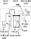
Top Development of experimental setup The experimental set-up shown in Fig. 2 consists of a vacuum chamber with a liquid nitrogen bath cooling system, a high vacuum pumping system and instrumentation and data acquisition system. A cylindrical liquid nitrogen vessel of diameter 200 mm and 300 mm length is welded to the top flange using a neck tube of 50 mm diameter and 80 mm length. The condenser section of the heat pipe to be tested will be attached to the bottom of the liquid nitrogen bath using clamps and screws. The top vacuum flange has two feed-throughs for connecting the leads of heater and other temperature sensors. Each feed-through has 37 pins. The feed-throughs are fixed to the top flange by screws with O-ring sealing. Heat load is applied to the evaporator section with the help of a manganin electric heater wound on the evaporator and a D C power source. The entire assembly of vacuum chamber and liquid nitrogen is made up of SS 304. The vacuum chamber is evacuated using an oil-diffusion high vacuum pumping system. The vacuum level in the chamber is measured using a cold-cathode penning gauge. For measuring the temperature profile of the heat pipe PT 100 sensors are used. The output of the temperature sensors and the power input to the heater are acquired by a PC using a Keithley scanner/DMM (model 2000) |
Top Fabrication of cryogenic heat pipe The design specifications of this heat pipe are as follows: |
The axial grooves are made by EDM wire cutting method. The machined heat pipe is cleaned with a solution of 50% nitric acid and 5% hydrofluoric acid. End caps are welded at the both ends of heat pipe using argon arc welding. The fill tube is fitted into the hole provided in one of the end caps and is brazed. Initially the heat pipe is degassed for about 6 hours. Then the evacuated heat pipe is weighed. The filling is carried out by evacuating and then backfilling with nitrogen and oxygen gas. In order to facilitate filling, the heat pipe is immersed in a liquid nitrogen bath. The heat pipe is weighed again and thus it is ensured that the required amount of gas is filled. The fill tube is then pinched off and brazed. The mass of the charge in the heat pipe is calculated by, |
 |
where m is the mass of the charge, Vv and Vi are the volume of the vapour and liquid respectively and ρv and ρi are the density of the vapour and liquid repectively. Assuming the operating temperature as 100 K, for nitrogen and thus the mass of nitrogen to be charged is 2.24 grams. |
Top Experimental Procedure The heat pipe is fixed to the bottom of the liquid nitrogen vessel with clamps and screws. The length of the heat pipe which is in contact with the liquid nitrogen vessel is regarded as length of the condenser. Over the evaporator length a manganin heater is wound uniformly and spirally. Two PT100 sensors are fixed each at the condenser and evaporator ends and one at the middle. The heat pipe is spirally wound with 10 layers of multilayer insulation (Jehier, France). The liquid nitrogen vessel surface is taped with aluminum adhesive foil and then wound with two to three layers of MLI. This is carried out in order to avoid the need for frequent filling of the liquid nitrogen vessel (see plate 3.5). The system is assembled and pumped down for about one day. The vacuum level attained is 1x 10⁻⁴ mbar. Liquid nitrogen is transferred into the liquid nitrogen vessel and allowed for the cool down of the heat pipe. After filling of liquid nitrogen the vacuum level improves to 2.9 × 10⁻⁶ mbar due to cryopumping. Then a heat load of 0.5 W is applied on the evaporator using a D.C. power supply. Data are acquired at regular intervals till a steady state is reached. Then the heat load is increased by 0.5 W. The above procedure is continued till the evaporator temperature goes above the critical temperature of the working fluid, which indicates dry-out of the evaporator. |
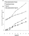
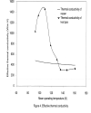
Top Results and Discussion Steady state performance of heat pipe Even though, the heat pipe was tested with 10 layers of multilayer insulation wound on that, the preliminary experiments showed that there was some amount of spurious heat flux on the heat pipe. In order to nullify this effect and compare the performance of heat pipe with that of copper, experiments were repeated on a solid copper rod of the same outer diameter. Fig. 3. shows the variations measured temperature difference across the heat pipe and the copper rod against heat load. The mean operating temperatures is also plotted in the same plot. It can be observed that the performance of the heat pipe is better for the heat load less than 3 W. For the heat loads greater than 3 W, the heat pipe's mean operating temperature exceeds the critical temperature (126.1 K) of the working fluid (nitrogen) and thus the heat pipe advantage is lost. Fig. 4. shows the variation of the effective thermal conductivity against mean operating temperature. In order to compare the effectiveness of the heat pipe with the data of other investigators, the estimated effective thermal conductivity values are multiplied by a factor by which the experimental performance of the solid copper rod is lesser compared to the data available in the open literature. The effective thermal conductivity of heat pipe increases up to 100 K mean operating temperature and decreases beyond 100 K. When compared with the results of Armaly [3], the effective thermal conductivity in the present study is about 2.2 times lesser at the mean operating temperature of 100 K. Since, in the present investigations the heat pipe was connected to the cold sink externally, the mean operating temperatures of the heat pipe is well above the normal boiling point (77 K) of liquid nitrogen. But even in these higher operating temperatures, the heat pipe's performance is better than that of copper and thus it is recommended to use the heat pipe even in the situations where the condenser need to be connected to the cold sink externally. Top Conclusion An experimental set-up for testing cryogenic heat pipes at about 77 K has been designed and developed. A nitrogen filled trapezoidal axial groove wick heat pipe was fabricated and tested. Experiments were conducted to determine the effectiveness of a heat pipe when it is connected to the cold sink externally. The results show that the effective thermal conductivity of heat pipe is about 2.9 times higher than that of copper at about 100 K. |
Top Acknowledgement The authors thank the Department of Science and Technology, New Delhi for funding this project under fast track scheme. |
Top Figures | Fig. 1: Schematic of a typical heat pipe operation
|  | |
| | Fig. 2: Schematic of experimental setup
|  | |
| | Figure 3.: Temperature difference and mean operating temperature against heat load
|  | |
| | Figure 4.: Effective thermal conductivity
|  | |
|
Table :
| | Length of the heat pipe | 180 mm | | Length of the evaporator section | 60 mm | | Length of the adiabatic section | 60 mm | | Length of the condenser section | 60 mm | | Outer diameter of the heat pipe | 12.72 mm | | Inner diameter of the heat pipe | 10.24 mm | | Wick-Trapezoidal axial grooves | 1.34x0.84x0.6(depth)mm | | Number of grooves | 17 |
| |
|