|
|
|
|
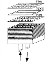
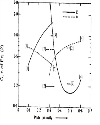
Heat transfer and flow friction studies on perforated plates using Fluent™ Kumar S. Sunil1, Research scholar, Nandi T. K.2, Assistant Prof. 1Cryogenic Engineering Centre, IIT, Kharagpur-721 302 2Cryogenic Engineering Centre, IIT, Kharagpur-721 302 Abstract Perforated plates usually find applications in matrix heat exchangers where heat transfer from one fluid to the other takes place by plate-fluid convection and plate conduction. The geometrical parameters that affect heat transfer and pressure drop characteristics are pore diameter, porosity, pore geometry and orientation of holes along the direction of fluid flow. In literature there are several correlations available for heat transfer and friction factor prediction. However, they differ significantly from one to other. In this paper an attempt has been made to obtain such correlations by modeling over a single peiiorated plate using Fluent™ solver. The model consists of a rectangular perforated test plate with two insulating spacers (one at the top and other at the bottom). Flow inlet and outlet are made through set of holes arranged either inline or offset with the perforated test plate. Studies have been done for varying Reynolds numbers from 100 to 1000. The results have been compared with the published data. Top Keywords Heat transfer, Flow friction, Coburn factor, Friction factor. Top | INTRODUCTION Perforated plates usually find applications in matrix heat exchangers where hot fluid and cold fluid streams pass through a set of holes as shown in Figure 1. Heat exchange among the fluids takes place by convection between the fluids and the plate, and by conduction along the plate material. Convection heat transfer takes place on the tubular surface of the holes and on the upstream and down stream faces of the perforated plate. Average heat transfer coefficient h is generally obtained from where i refers to the surface where convection heat transfer takes place. There are several works reported in literature for determining correlations for convection heat transfer on perforated plates. A large fraction of works [1-7] expressed Nusselt number in the form where C and n are the constants that depend on the plate porosity. Venkatarathnam and Sarangi [8] summarized these results and presented in a graphical form shown in figure 2. |
 |
 |
Figure 2 shows that there are significant disagreements between the data obtained by different authors. This is probably because convective heat transfer mechanism over a perforated plate depends on many factors such as i) plate porosity ii) plate thickness iii) spacer thickness iv) hole diameter etc. An appropriate correlation should include these factors. Recently Krishnakumar and Venkatarathnam [9] conducted a series of tests and expressed Nusselt number as functions of In case of a stack of perforated plates, the holes of one plate may be inline or offset with the immediate upper or lower plate. There can be significant differences in heat transfer depending on hole arrangements. |
 |
In this paper, a single perforated plate has been numerically modeled using Fluent™ for studying heat exchange between two fluid streams. The objectives are (i) to study the effects of various geometrical and flow parameters on the heat transfer and flow friction and (ii) to obtain rationalized correlations for the purpose of designing an MHE. |
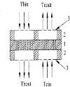
Top THE MODEL For determining heat transfer coefficients and flow friction parameters, heat transfer from a hot fluid to a cold fluid has been numerically modeled over a single perforated plate. The geometrical arrangement is schematically shown in figure 3 where a perforated Cu plate is arranged with spacers at top and bottom. For obtaining a realistic flow situation of an MHE, fluid inlets and outlets are given only through the flow guiding planes as indicated in figure 3. The holes in the flow guiding planes may be considered equivalent to the holes of perforated plates above and below the test plate. With reference to the hole geometry of the test plate, the holes in the flow guiding planes can be arranged in such a way that one can obtain inline or offset hole patterns. In all cases, hexagonal geometry is chosen for arranging the holes. |
Modeling by using Fluent ™ involves drawing an object and meshing by using GAMBIT. The mesh file is then exported to Fluent for numerical solution. Because of the presence of a large number of small diameter (0.4 to 0.8 mm) holes, meshing of a perforated plate is rather complicated. Usually a large number of nodes are generated depending upon plate dimensions, porosity, pore diameter etc. This is why in the proposed study, modeling is done only over a single perforated plate. |
For meshing faces, quadrilateral map and quadrilateral pave mesh schemes have been used. While meshing volumes, hexahedral map and hexahedral cooper meshing schemes are used. Because of the presence of small diameter holes, we have rather limited choices on the mesh size. For example for a hole size of 0.5 mm diameter, a mesh size of 0.15 mm appears reasonable. Using mesh of further small size may lead to increase in round off errors. However, accuracy of the results is checked from the energy balance where heat rejected by the hot fluid should be equal to the heat received by the cold fluid. Wall boundary conditions have been defined for top, bottom, tube faces and the central partition face separating the hot and cold fluid streams. Solid boundary conditions are defined for solid portion of plate excepting the holes and for the spacer volumes at the top and bottom. Figure 4 shows the top view of the model after meshing in Gambit. |
In Fluent, material definitions, thermal boundary conditions at flow inlet and exit, momentum boundary conditions at flow inlets, continuum boundary conditions for the fluid, solid, and the wall etc, are defined. Because of single plate only a small value of temperature difference (5–10 deg) is used between Thin and Tcin. Solution is obtained after proper initialization, convergence criteria*etc and giving number of iterations. |
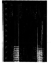
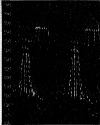
Figures 5 and 6 show flow velocity vectors for inline and offset configurations respectively. |
Top SAMPLE RESULTS AND DISCUSSIONS Fluent generates heat transfer coefficients for front surface, tubular surface and bottom surface of the plate separately. A set of sample data generated by Fluent is shown in Table 1. From these data average heat transfer coefficients for hot and cold fluid sides are obtained by area weighted average approach (Eq. (1)). Heat transfer coefficient is usually expressed in the form of a non-dimensional term called Colburn factor j defined as |
Studies have been done for varying Reynolds numbers from 100 to 1000 which is the most probable range of operation in MHEs [10]. Reynolds numbers are varied by changing the mass flow rate of the fluids. |
The pressure drop is due to (a) frictional pressure drop in the tubular surface of perforations (b) contraction loss at the entry and (c) expansion loss at the exit. Fluent displays static pressure drop directly in the pressure contour panel. The flow friction data is presented in the form of Fanning friction factor f defined as |
Figure 7 shows a comparison between computed data and the experimental data available in literature [9], Colburn factor j and Fanning friction factor f are plotted as a function of Reynolds number. It is observed that experimental data lies in between the inline and offset data generated by Fluent. This may be due to the fact that the heat exchanger used in reference [9] has certain amount of offset hole arrangement. |
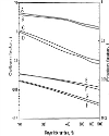
Figure 8 shows variation of j and f factors with Reynolds number for different plate thicknesses. It is seen that the heat transfer coefficient j and friction factor f increase with increase in plate thicknesses for the same hole diameter (d), spacer thickness (s) and plate porosity (p). |
Offset: A, B, E, F, Inline: C, D, G, H |
Colburn factor: E, G (tp=0.75mm) and |
Friction factor: A, C (tp=0.75mm) and B, D (tp= 0.5 mm) |
The effects of accelerating fluid between plate and spacer as well as significant increase in local turbulence leads to substantially increased local heat transfer with decreased s/l ratio. Hence there is an increased overall heat transfer coefficient for longer tube lengths for same spacer thicknesses or smaller s/tp ratio. |
Top CONCLUSIONS In this paper heat transfer and flow friction studies over a single perforated plate have been done using Fluent ™. Results have been compared with the literature reported experimental data. Studies are being continued for obtaining data under various geometrical and operating conditions. Using these data rationalized correlations for heat transfer and flow friction can be obtained and used in practical design of an MHE. |
Top NOMENCLATURE ACKNOWLEDGEMENT The authors thankfully acknowledge the support given by the Department of Science and Technology, Govt, of West Bengal for carrying out this work. |
Top Figures | Figure 1.: Construction of an MHE
|  | |
| | Figure 2.: Comparison of constants C and n in the relation Nu=CRen as a function of plate porosity by different authors
|  | |
| | Figure. 3: Longitudinal view of the test plate and spacers assembly (1 = perforated test plate, 2 = insulating spacers, 3 = flow guiding planes)
|  | |
| | Figure. 4: The model after meshing in Gambit
|  | |
| | Figure 5.: Flow velocity vectors for inline arrangement
|  | |
| | Figure 6.: Flow velocity vectors for offset arrangement
|  | |
| | Figure 7.: Comparison of j and f with experimental data [9] at p=0.21, s/tp=1, tp/d=0.511 (friction factor: A=experimental, B and C= our works with offset and inline geometry respectively. Colburn factor j: E=experimental, D and F= our works with offset and inline geometry respectively.)
| 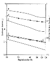 | |
| | Figure 8: Comparison of j and f for varying plate thicknesses at p=0.21, s=0.4mm, d=0.78mm
|  | |
|
Tables | Table 1: Surface heat transfer coefficient (W/m2K) values given by Fluent
| | Tube-cu-right | 218.755 | | Surface-cu-right-bottom | 287.49 | | Surface-cu-right-top | 224.58 | | Tube-Cu-left | 150.91 | | Surface-cu-left-bottom | 153.88 | | Surface-cu-left-top | 196.77 |
| | :
| | A | heat transfer area, m2 | | d | diameter of perforation, m | | f | fanning friction factor | | G | mass velocity, kg/m2s | | h | Convection heat transfer coefficient, W/m2K | | j | Colburn factor | | Nu | Nusselt number | | Re | Reynolds number | | μ | Absolute viscosity, kg/m-s | | Pr | Prandtl number | | tp | thickness of perforated plate, m ? | | L | length of heat exchanger, m | | s | thickness of spacer, m | | p | porosity of perforated plate | | Thin | hot fluid inlet temperature, K | | Tcin | cold fluid inlet temperature, K | | ∆p | pressure drop, Pa | | p | density, kg/m3 |
| |
| | |
|
|
|