
|
|
|
(3.142.197.212)
|
|
Users online: 12105
|
|

|
|
|
|
|
Ijournet
|
|
|
|
|
|
|
Experimental studies on Tube-In-Tube compact heat exchanger Natarajan V.1, Kumar P. Senthil2 1Sathyabama University, Chennai, Tamil Nadu 2K.S.R. College of Engineering, Thiruchencode, Tamil Nadu Abstract Tube-in-tube compact heat exchangers with a new type of extended surface based on thin wire mesh are fabricated with a compactness of 1917.12 m2/m3 and 5847.56 m2/m3. Experiments are conducted in these compact heat exchangers with R-134a and mixture of hydro carbons (LPG). The effectiveness of the heat exchangers was calculated using the experiment data and it was found that the effectiveness of heat exchanger-1 is 78% and heat exchanger -2 is 83% for R-134a.The effectiveness of heat exchanger-1 is 61% and heat exchanger -2 is 79% for mixture of hydro carbons (LPG). In the case of heat exchanger-1 the temperature difference in the hot end is 10K to 20K and the cold end is 4K to 5K. The pinch point was occurred in the cold end. In the case of heat exchanger-2 the temperature difference in the hot end is 13K to 16K and the cold end is 12K to 14K. In this paper, details about the new tube-in-tube type compact heat exchanger, experimental setup, results and conclusions are discussed. Top Keywords Compact heat exchanger, Effectiveness, Pinch point, Compactness. Top | INTRODUCTION Heat exchangers are one of the most critical components in any liquefaction/refrigeration system. Its effectiveness governs the efficiency of the whole system. The major requirement of these heat exchangers, working in the low temperature range, is to have high effectiveness [1]. Development of a high effectiveness compact heat exchanger that can be used under low temperature conditions is one of the important requirements for aerospace, gas turbine power plant and other industries. The design of heat exchangers is very important from the system performance point of view. The design should take various losses, occurring during the exchange of heat into consideration. The performance of the heat exchanger is governed by various parameters like mass flow rates, pressures and temperatures of working fluids, etc. Heat exchanger effectiveness takes into consideration the limitations of heat transfer between two heat exchanging streams due to these parameters [2], |
There are two major streams in developing compact heat exchangers, one is the primary surface type and other is tube-in-tube type. Primary surface types have a potential to achieve the demanding requirements at relatively low cost as they do not need a brazing process and therefore intensive investigations are going on[3,4]. Tube-in-tube types, on which this study focuses, have been being investigated for decades and fundamental information is available in handbooks and literature. For further evolution of tube-in-tube types, development of effective extended surface would be a key [5]. |
In this paper, a new type of extended surface based on thin wire mesh is proposed. Use of the wire mesh as extended surface has many advantages. A large surface area density can be achieved particularly when thin wires are used. Geometric parameters of wire mesh such as the wire diameter, the cross sectional shape of wire and mesh diameter can easily be controlled, which allows to have many design options to achieve heat transfer requirements. There is a wide variety of material available too. If the wire diameter is small, a mesh will form a flexible structure, unlike the conventional rigid mesh, which is also an advantage because such a flexible structure will release the thermal stress. In addition, there is no problem for mass production and therefore it has a potential to be cost effective. |
Top Nomenclature Tube-In-Tube Compact Heat Exchanger The definition of compactness is quite arbitrary matter. The ratio of the heat transfer surface area on one side of the heat exchanger to the volume can be used as a measure as the compactness heat exchangers. The heat exchanger having a surface area density on any one side greater than about 700m2/m3 quite arbitrary is referred to as a compact heat exchanger regardless of its structural design [6]. The human lungs with an area density of about 20000m2/m3 are the most compact heat and mass exchanger. |
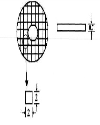
Top Dimensions of Tube-in-tube Compact Heat Exchanger The copper wire mesh of size16/inch is Selected which suited to the requirement. |
Thickness of wire mesh: 0.7mm |
No. of meshes in a d isc: 60 |
Top Fabrication details of Tube-in-tube Compact Heat Exchanger The copper tubes were cut according to the required length. The cutting operation is done by means of a tube cutter. Then the inner tube is placed inside the outer tube is kept within by using copper plates using the brazing process. Before brazing the outer tube is drilled to locate the inlet and outlet tubes. Then these inlet and outlet tubes are also brazed. |
Copper meshes are placed in the form of small discs in between the tubes and the copper wire is wound like a coil which is inserted in the inner tube of CHE-1.The small copper discs can be made by means of die arrangement. It is to be noted that the copper discs are dumped in to the space between the tubes of CHE-1. In the CHE-2 the copper discs are inserted in the inner tube and the copper wired coil is placed in between the tubes. Joining of copper tubes is made up by means of brazing process. A cut sectional view of proposed CHE is shown below. |
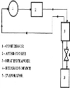
Top Experimental Procedure In this experimental work, R-134a and mixture of hydro carbons (LPG) are used as working fluid in both the streams. Resistance temperature detectors (RTD) are used as temperature sensing elements. These sensors are connected to a digital temperature display and are placed on the heat exchanger such that the inlet and outlet of both the hot and cold streams. The effective length of CHE is insulated with colex polyethylene foam material. The hot stream is allowed to pass through the inner tube and cold stream is allowed to pass through the outer tube of the CHE. |
The fluid streams are allowed to pass through the compact heat exchanger in opposite directions, because of the effectiveness in the counter flow is greater than the parallel flow. The readings are observed and tabulated. |
Top RESULTS AND DISCUSSION The analysis of these tube-in-tube compact heat exchangers were performed more easily by utilizing a method based on the effectiveness of the heat exchanger in transferring a given amount of heat. The effectiveness method also offers many advantages for analysis of problems, in which a comparison between various types of heat exchangers must be made for purpose of selecting the type suited to accomplish a particular heat transfer objective, The heat exchanger effectiveness as |
The actual heat transfer may be computed by calculating either the energy lost by the hot fluid or the energy gained by the cold fluid. |
For the counter flow exchangers, |
To determine the maximum possible heat transfer for the exchanger, first recognize that this maximum value could be attained if one of the fluids were to undergo a temperature change equal to the maximum temperature difference present in the exchanger which is the difference in the entering temperature for the hot and cold fluids. The fluid, which might undergo this maximum temperature difference, is the one having the minimum value of mc because requires that the energy received by one fluid be equal to that given up by the other fluid. If the fluid with the larger value of mc go through the maximum temperature difference, this would require that the other fluid undergo a temperature difference greater than the maximum possible heat transfer is expressed as, |
 |
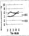
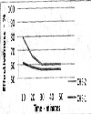
The minimum fluid may be either the hot or cold fluid, depending on the mass flow rates and specific heats. The subscripts on the effectiveness symbols designate the fluid, which has the minimum value of mc. For the counter flow, The effectiveness of any heat exchanger is influenced by the occurrence of pinch point in the counter flow chart as well as the thermodynamic process of the system. |
The pinch point in the counter flow chart is the distance between two-stream line of the hot and cold fluids is less. The temperature difference in the cold end and the hot end will be minimum means the pinch point will occur and the effectiveness of the heat exchanger is high. During the pinch point the transfer of the heat by the process of isothermal. |
The pinch point in the thermodynamic process of the system may vary from fluid to fluid. For the pure substances, the pinch point is above the critical point i.e., in the atmospheric conditions. Due to this, the state of the fluid before entering the expansion device is fully gas. This gas is expanded and the phase is changed to the liquid. The loss in heat exchanger is more and the heat transfer rate will be 70K to 80K. Because of this reason the effectiveness will reduce. |
Some fluids like R-134a and mixed refrigerants (LPG) have the pinch point is below the critical point and at very low temperature region. So the state of the fluid before entering to the expansion device is liquid. The loss in the heat exchanger is very less and the temperature rate will be 5K to 10K. The effectiveness of the heat exchanger is high in this case. |
The effectiveness achieved in this tube-in-tube compact heat exchangers were |
61% and 79% using mixture of hydro carbons |
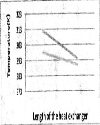
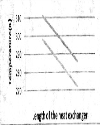
Top CONCLUSION Use of thin metal wire mesh as an extended heat transfer surface is proposed. The performances of the compact heat exchangers are experimentally evaluated. In the compact heat exchanger-1, the temperature difference in the hot end is 10K to 20K and the cold end is 4K to 5K. The pinch point was occurred in the cold end. In the compact heat exchanger-2, the temperature difference in the hot end is 13K to 16K and the cold end is 12Kto 14K. |
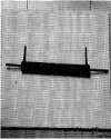
Top Figures | Figure 1.: Three Dimensional View of Tube-In-Tube CHE
|  | |
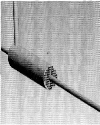
| | Figure 2.: Three Dimensional Cut Section of Tube-In-Tube CHE
|  | |
| | Figure 3.: Dimensional View of Wire Mesh Disc
|  | |
| | Figure 4.: Experimental Set Up With Compact Heat Exchanger
|  | |
| | Figure5.: Effectiveness of CHE using R-134a Refrigerant
|  | |
| | Figure 6.: Effectiveness of CHE using Mixture of Hydro Carbons (LPG)
|  | |
| | Figure 7.: Temperature Distribution for CHE-1
|  | |
| | Figure 8.: Temperature Distribution for CHE-2
|  | |
|
Table :
| | CHE | compact heat exchanger | | Cp | specific heat capacity at constant Pressure (kJ/kgK) | | di | inner tube diameter (mm) | | d0 | outer tube diameter (mm) | | h, | heat transfer co-efficient of inner tube (W/m2K) | | h0 | heat transfer co-efficient of outer tube (W/m2K) | | k | thermal conductivity (W/mK) | | L | length of heat exchanger | | mc | flow rate of the cold fluid stream (Kg/sec) | | mh | flow rate of the hot fluid stream (kg/sec) | | NTU | number of transfer units | | Nu | averged Nusselt number | | Re | Reynolds number | | t | time (min) | | P1 | suction pressure (bar) | | P2 | delivery pressure (bar) | | T1 | inlet temperature of hot end (K) | | T2 | outlet temperature of cold end (K) | | T3 | inlet temperature of cold end (K) | | T4 | outlet temperature of hot end (K) | | ΔTh | temperature difference in the hot end (K) | | ΔTC | temperature difference in the cold end (K) | | ε | effectiveness(%) |
| |
| | |
|
|
|
|
║ Site map
║
Privacy Policy ║ Copyright ║ Terms & Conditions ║

|
|
|
751,608,961 visitor(s) since 30th May, 2005.
|
|
All rights reserved. Site designed and maintained by DIVA ENTERPRISES PVT. LTD..
|
|
Note: Please use Internet Explorer (6.0 or above). Some functionalities may not work in other browsers.
|