Development of vapour shielded liquid helium dewar Goyal Mukesh1, Menon Rajendran S.1, Singh Trilok1 1Cryo-Technology Division, Bhabha Atomic Research Centre, Trombay, Mumbai-400 085 Abstract This paper describes the development of a 100L nominal capacity liquid helium (He) Dewar which uses multi-shield insulation system utilizing the cold from evaporated vapour of the stored cryogenic liquid. Heat in-leak design calculations are done using Finite Difference Method (FDM) by discretisation of Dewar neck into smaller elements and solving the energy balance taking care of variable neck material properties, variable vapour properties, heat in-leak through super-insulation, conductive heat transfer through neck and vapour, convective heat transfer from neck to vapour etc. A computer program is developed using Visual Basic Script of Microsoft Excel coupled with Gas property software package. Positions of He vapour cooled thermal shields are optimized for minimum heat in-leak to liquid helium (LHe). Mechanical design and fabrication of Dewar is done using ASME Boiler and Pressure Vessel code Section II, V, VIII Division-1 and section IX. Vacuum leak tightness of the Dewar is evaluated using He mass spectrometric leak detector (MSLD). Performance evaluation is done using liquid nitrogen (LN2). Top Keywords Liquid Helium Dewar, Multi-shield Insulation System, Heat in-leak. Top |
INTRODUCTION LHe Dewar is a critical component of any He liquefaction system. Because of very low latent heat of LHe, control of heat in-leak into LHe is very critical. Standard 100L nominal capacity LHe Dewar with 1% per day evaporation rate are available with reputed manufacturers [1], this kind of low evaporation rate corresponds to total heat in-leak of just 0.03 watts to LHe. In such case proper design of super insulation, thermal shielding, shield cooling and design of Dewar neck becomes very critical. |
Heat in-leak to cryostat has been experimentally analysed by various authors [2-5]. Heat in-leak through super insulation has been analysed both analytically and experimentally [6-15] by many authors. Exact solution of all the equations describing different mechanisms of heat exchange in the cryostat is not possible. For optimization calculations many simplifying assumptions are used as accurate values of all the relevant physical parameters are not available and a method for solving them are not known. Therefore numerical modeling [2, 16] and computer program [17] become essential for the optimization of heat in-leak into a cryostat. |
Top DEWAR HEAT INLEAK ANALYSIS AND SHIELD POSITION OPTIMIZATION Heat in-leak calculations and optimization of vapour cooled thermal shields position is done using FDM [18] by discretisation of Dewar neck into smaller elements and solving the energy balance equations. |
Assumptions The temperatures of the outer vessel, inner vessel containing liquid and thermal shields are constant over their entire volume. Steady state heat flow is considered. Laminar heat transfer is assumed between neck and vapour. Nusset number for this case remains constant throughout the neck height [19]. Specific heat of the vapour is obtained from GASPAK (© copyright Cryodata Inc.) dll [20]. Specific heat cannot be taken as constant especially near boiling point. Thermal conductivity of structural material and vapour is temperature dependent. Thermal conductivity of vapour is taken from GASPAK (© copyright Cryodata Inc.) dll and Curve fit equations are used for temperature dependent thermal conductivity of SS-304L material used for neck [21]. Heat radiation emissivity is function of material, surface treatment and temperature [6], Practical values mentioned by many authors differ to a great extent. In the calculations emissivity values of 0.03 is used throughout although temperature dependent emissivity can be used in the calculation algorithm. Effect of heat radiation passing through vapour side of neck is neglected assuming the same can be reduced sufficiently by the use of multiple baffles. Optimization of thermal shield position If thermal shield is attached very near to LHe(to get lower shield temperature) He vapour will not get sufficient area to extract heat by convection therefore heat coming from thermal shield will be conducted to LHe through neck instead of being carried away by He vapour. Lower shield temperature also increases radiation load from outer vessel to shield which in turn increases shield temperature. Therefore there is an optimum position where shield shall be attached to neck to get minimum LHe evaporation. The same logic can be extended for multi-shields. Energy balance and heat transfer equations ith element of neck ith element of He vapour Last element of helium vapour Liquid helium: Shield-2: Shield-1: Convection between He vapour and neck [19]: d = Hydraulic diameter, Nu= Nusset number Heat In-leak through super insulation (conduction +radiation) [9]: εTR= 0.03, Cs= 4.48×l010, Cr= 4.48x10⁻¹², N= layers/cm, δ= super insulation thickness Heat transfer through vacuum alone (radiation+ free molecular conduction): Top DEWAR MECHANICAL DESIGN AND FABRICATION Mechanical design and fabrication of Dewar is done using ASME Boiler and Pressure Vessel code Section II, V, VIII Division-1 and section IX. Design pressure for Dewar is 3bars(g). Inner vessel is a 2mm thick cylinder of 558.8mm OD, 350mm height with ASME standard torispherical head of 2mm thickness. Outer vessel is a 3mm thick cylinder of 711.2mm OD, 620mm height with ASME standard torispherical head of 3mm thickness. |
Inner neck is 45mm ID, 48mm OD tube of 400mm height. Outer Neck is 66.9mm ID, 73mm OD tube of 150mm Height. 1 mm thick Cu sheets are used as vapour cooled thermal shields. Thermal shield are directly attached to Dewar neck by silver brazing. Shield-1 is attached at 150mm height and shield-2 is attached at 250mm height. Jehier make super insulation (INSULRAY IR 305-10) is used for radiation shielding. Total 10 layers are used between LHe inner vessel and shield-1, 20 layers between shield-1 and shield-2, 20 layers between shield-2 and outer vessel. Charcoal packets connected to inner vessel and radiation shield are used for cryo-adsorption and long term vacuum retention. Vacuum leak tightness of the Dewar is evaluated using He MSLD. Gross leak tightness of inner vessel is better than 5x10⁻⁹mbar.l/sec while gross leak tightness of outer vessel is 1x10⁻⁷mbar.l/sec. |
Top RESULTS OF HEAT IN-LEAK CALCULATIONS LHe as working cryogenic fluid In the ideal case (zero heat in-leak through super insulation) there will be heat inleak equivalent of 46.5 liters per day of LHe if neck is not cooled by He-vapour and 1.7 liters per day of LHe if there is ideal heat exchange in the neck i.e. vapour temperature is same as neck temperature. LN2 as working cryogenic fluid In the ideal case (zero heat in-leak through super insulation) there will be heat inleak equivalent of 0.82 liters per day of LN2 if neck is not cooled by N2-vapour and 0.55 liters per day of LN2 if there is ideal heat exchange in the neck i.e. vapour temperature is same as neck temperature. Top PERFORMANCE EVALUATION AND DISCUSSIONS To start with performance evaluation is done using LN2. Heat in-leak design calculations are accordingly modified for change of fluid i.e. from He to N2. Empirical correlation used for heat in-leak through super insulation, neglected the effect of free molecular conduction and assumes that pressure is below 10−6 mbar. Molecular conduction parameter can be added to take care of heat in-leak due to free molecular conduction in case of vacuum poor than 1CT6 mbar (but still in molecular conduction range). Average evaporation rate of LN2 for one month hold-up period measured with drop in LN2 was 1.14 liters per day while the vacuum during this period was stable at 3.5×10⁻⁴ mbar (Static vacuum without vacuum pump.). Theoretical calculations as described above estimated the LN2 evaporation rate of 1.2 % at this vacuum level of 3.5x10⁻⁴ mbar. Further performance evaluation with LHe is planned for the verification of design and optimization methodology. |
Top ACKNOWLEDGEMENTS This work was carried out under the Department of Atomic Energy, Govt, of India programme with active support of ail the staff of Cryo-Technology Division, BARC, Mumbai. |
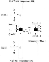
Top NOMENCLATURE Figures | Figure 1.: Heat Transfer Model of Dewar Neck
|  | |
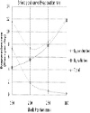
| | Figure 2.: Heat in-leak to LHe Dewar, Single Thermal Shield, 20 layers between Outer vessel and shield, 30 layers between shield and LHe
|  | |
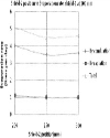
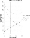
| | Figure 3.: Heat in-leak to LHe Dewar, Two Thermal Shields, 20 layers between Outer vessel and shield-2, 20 layers between shield-2 and shield-1, 10 layers between shield-1 and LHe, Shield-1 at 100 mm
|  | |
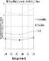
| | Figure 4.: Heat in-leak to LHe Dewar, Two Thermal Shields, 20 layers between Outer vessel and shield-2, 20 layers between shield-2 and shield-1, 10 layers between shield-1 and LHe, Shield-1 at 150 mm.
|  | |
| | Figure 5.: Heat in-leak to LN2 Dewar, Single Thermal Shield, 20 layers between Outer vessel and shield, 30 layers between shield and LN2
|  | |
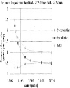
| | Figure 6.: Heat in-leak to LN2 Dewar, Two Thermal Shields, 20 layers between Outer vessel and shield-2, 20 layers between shield-2 and shield-1, 10 layers between shield-1 and LN2, shield-1 at 150mm, shield-2 at 250mm.
|  | |
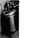
| | Figure 7:: Experimental LHe Dewar
|  | |
|
Tables | Table 1: Heat in-leak to LHe Dewar (liters per day of LHe) No intermediate thermal shields, 50 layers of super insulation.
| | By conduction | By Radiation | Total | | 0.7 | 42,3 | 43 |
| | | Table 2: Heat in-leak to LN2 Dewar (liters per day of LN2), NO intermediate thermal shields, 50 layers of super insulation.
| | By conduction | By Radiation | Total | | 0.41 | 0.64 | 1.05 |
| | :
| | Ac | Cross sectional area | | Ai | Surface area of inner vessel | | As | Surface area of element for Radiation and convection | | Ashieldl | Surface area of shield-1 | | Ashield2 | Surface area of shield-2 | | c | Heat capacity of vapour | | dy | Height of neck and vapour element | | E | Radiation heat flux/heat flux through thermal shield to neck element | | E1, i | Heat flux from shield-1 to inner vessel | | E2, l | Heat flux from shield-2 to shield-1 | | E0,2 | Heat flux from outer vessel to shield-2 | | h | Heat transfer coefficient | | Hfg | Latent heat of vaporization | | k | Thermal conductivity | | M | Molecular weight of gas | | m | Mass flow rate | | P | Gas pressure | | Q | Heat flow, | | R | Universal gas constant | | T | Temperature | | α | Accommodation coefficient | | γ | Heat Capacity Ratio, Cp/Cv | | δ | Emissivity | | σ | Stephan-Boltzmann constant(5.67×10⁻⁸ W/m2K4) | | Subscript | | abs | Absorption | | C | Cold | | eff | Effective | | f | Fluid(vapour) | | H | Hot | | i | Order number of elements | | n | Neck | | rt | Room Temperature |
| |
|