Reliability and functional testing scheme for cold circulating pumps required to cool large size fusion grade superconducting magnets and cryo-pumps Vaghela H.1, Bhattacharya R.1, Sarkar B.1, Badgujar S.1, Shah N.1 1ITER-INDIA, Institute for Plasma Research, Bhat, Gandhinagar-382428, India Abstract Forced flow cooling using supercritical helium is the most preferable method due to the distinct advantages over the other cooling procedures for the superconducting magnets and cryo-pumps in fusion research devices. The flow requirements are high to fulfill the stability requirement of the magnet system during all operational modes. The flow requirements are met with cold circulation pump at 4 K level. These pumps require state of the art design due to constraints from temperature and associated process requirements with a demand of high efficiency. The future requirement of the future fusion research reactor (ITER) is foreseen as ∼2.7 kg/s mass flow rate with adiabatic efficiency > 70%. Against the future requirement, the maximum capacity ever built till now has a capacity of 1.2 kg/s mass flow with adiabatic efficiency-60%. Therefore, the up scaling of existing cold circulating pumps with improvement of efficiency is necessary to meet the future requirement. This paper discusses the major risks associated with cold circulating pumps and a test proposal with basic testing scheme to validate the performance. Top Keywords Cold circulating pump, Testing scheme, Risk. Top |
INTRODUCTION Superconducting (SC) magnet systems are considered to be one of the most important sub-systems for fusion machine. Large SC magnet systems, in size and field are foreseen for a fusion device. At the same time, to maintain the functions of SC magnets system efficiently, cryogenic system plays a vital role to support the operation of SC magnets. The SC magnets of fusion machines are normally cooled with forced flow helium at a temperature level of 4 K. The cryogenic system provides necessary cooling power to maintain the magnets in its superconducting state despite several disturbances arises during the operation of fusion machines [1]. |
Supercritical Helium (SHe), one of the phase of helium at 4 K temperature level are considered as the most favorable fluid, to be used as cryogens for cooling the SC magnets of the fusion machines. The flow requirement through the magnet system arises from the stability point of view during all operational modes. For the fusion SC magnets, the flow requirements are very high, which cannot be provided by the warm compressors of a cryogenic refrigerator. This is the process limitation of a cryoplant; therefore, an alternate solution has been foreseen. Such flow requirements are met by implementing a Cold Circulation Pump (CCP) at 4 K level, which helps in circulating the cryogen through the SC magnets. |
Top COLD CIRCULATING PUMP These pumps functions like a normal pump for any other fluids but require very special design due to constraints from temperature and associated issues. |
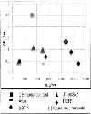
The future requirement of one of the cold circulating pumps in fusion research reactor foreseen is ∼2.7 kg/s mass flow rate and 0.4 bar head [2]. The adiabatic efficiency requited is > 70%. Against the future requirement, the maximum capacity ever built till now has a capacity of 1.2 kg/s mass flow rate and 0.4 bar pressure head with adiabatic efficiency∼60% [3]. Figure 1 shows the global scenario of CCPs in terms of existing and future requirements [2,3,4,5,6]. |
So the up-scaling of existing machines with improvement of efficiency is necessary to meet the requirement of future fusion research reactor. The operation of fusion research reactor is pulsed in nature and large pulsed heat load are deposited in the magnet system due to electromagnetic field variation and nuclear heating. The pulsed operations of fusion research reactor make it necessary to study the dynamic behavior of cold circulating pump and cold compressor during operation. |
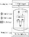
Top SYSTEM DESCRIPTION Once a CCP is implemented in a SC magnet cooling circuit, a closed loop operation must be foreseen. This also means that the heat generated by the pump, must be dissipated before entering the SC magnet circuit, in order to ensure that the cryogen (fluid) temperature is respected at the inlet of the SC magnets. Figure 2 shows the schematics of one such cooling circuit. |
CCP is used to provide forced flow cooling using supercritical helium to the SC magnets and cryopumps. To maintain certain temperature of the circulating fluid i.e. supercritical helium and to reject the heat coming from the magnets or cryopump, a heat exchanger is used which is immersed in liquid helium (LHe) bath. |
Cold compressor attached to the LHe bath compresses and transfers the vapour generated due to heat rejection by the heat exchanger in LHe bath and due to vapour fraction of the Joule-Thomson (JT) valve to the cryoplant. Cold compressor suction pressure is maintained according temperature (corresponds to saturation pressure) desired in LHe bath, while the discharge pressure is kept and maintained taking in to account the pressure level at low pressure (LP) of warm compressor station of cryoplant and line hydraulic resistance. The level in the LHe bath is continuously maintained by supplying the liquid helium using the JT valve-from the downstream cold helium coming from the cryoplant. |
Top RISK ANALYSIS The tentative requirements of ITER CCPs during the nominal operating mode for Toroidal Field (TF), Structure (ST), Central Solenoid (CS), Poloidal Field (PF) and Cryo-pump (CP) is summarized in Table-1 [2] |
$-Calculated power considering 70% adiabatic efficiency |
CCP of Structure requires the maximum mass-flow rate 2.7kg/s whereas CCP of CS and TF required maximum head 0.135 MPa. Efficiency requirement is >70% for nominal requires∼16 months continuous operation (operation between two long term maintenance) of CCPs [1], This requirement calls for very reliable and long life bearing system for CCPs. To cope the transient heat load of the applications, flow rate variation through variable speed of CCP is foreseen. |
The CCP with 2.7 kg/s mass flow rate capacity is yet not built; hence the development of such large capacity CCP is desirable. |
The risk associated with the CCP has been identified for the five categories, |
Functional failure Mechanical failure Electrical/instrumentation failure Controllability failure Other failure
Top BASIC TEST PROPOSAL The future requirements of the CCPs clearly indicate the up-scaling of the existing CCPs with efficiency requirement >70% and robust design to withstand transient process conditions. Reliability of CCP is critical’ to ensure the required overall availability of the ITER machine. Pre-series test of cold circulating pump is proposed which will develop the confidence and mitigate the associated risks. |
The test objectives are summarized based on the current understanding and risk identification. Test objectives are classified in to two categories (A) primary objective (B) secondary objectives. |
Primary objectives, Pre-series test of cold circulator at its nominal operating conditions to obtain CCP's actual performance results (characteristic curves), which include parameters like (a) flow rate, ṁ (b) Flead, ∆P (c) Efficiency, η (d) Speed, Flz and (e) Power To validate the rate of change of mass flow rate. Create the pressure variation conditions at the inlet of CCP Create the temperature variation conditions at the inlet of CCP (this objective is restricted depending upon capability of the test facility) Behavior of CCP under different pressure head (∆P) Minimum mass flow rate operation Maximum speed (110%) operation
Secondary objectives, To perform the replacement of motor, bearing, impeller and shaft all together called as cartridge. This to ensure that the replacement of cartridge can be performed in stipulated time. To verify the controllability of the CCP Bearing performance (can be a separate test at room temperature) Vibration and noise level measurement
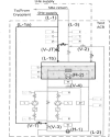
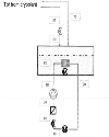
Figure 3 shows the preliminary testing scheme of the CCP. Cool-down of the test cold box together with LHe bath and closed testing loop will be done through the line (L-1) coming from the cryoplant. This line (L-1) is divided in to two paths; one path (L-1 a) will fill as well as cooldown the closed testing loop by valve (V-1) and second path (L-1b) will do cool-down of the LHe bath. Return line (L-2) will be connected to the return line (L-3) by emptying valve (V-2). During cool-down required flow will be circulated in the closed testing loop by keeping the valve (V-3) in closed condition and with CCP in stop condition. When temperature reaches near 5K within a closed loop, CCP will be started with slow speed. LHe bath will be filled with liquid using Joule Thomson (JT) valve (V-JT) in the line (L-1b) and level will be maintained. Filling valve (V-1) and emptying valve (V-2) will be slowly closed and valve (V-3) will be slowly opened after the required pressured is attained in the closed loop. Circulation will be maintained in closed testing loop using CCP at its rated speed. Test of CCP will be carried out under different test scenario. Preliminary testing scheme includes the minimum measuring points for the test. ΔP across the CCP will be created using valve (V-3). Pressure variation condition at the inlet of CCP can be created using filling valve (V-1) and emptying valve (V-2), however, maximum pressure that can be generated depends on the pressure available from the cryoplant. Temperature variation at the inlet of CCP can be performed using heater (H-1) or using bypass valve (V-4). However, temperature variation is limited to the cryoplant capacity. Cryoplant capacity can be enhanced with the additional source of liquid helium. This will enabie the test of CCP beyond the cryoplant capacity, however, cold helium recovery to be managed if the additional LHe source is used. Top PROCESS EVALUATION Figure 4 shows the simplified process scheme with assigned node number for the process evaluation of a CCP having 2.7 kg/s mass flow rate and 0.04 MPa pressure head. |
Process evaluation of the testing scheme is carried out assuming, |
Steady state condition at ∼4 K temperature level 70% adiabatic efficiency of CCP Supercritical helium at 0.4MPa and 5 K available from the cryoplant LHe bath temperature 4.2K Total static heat load is 100 W at 4.5K Heater power is set at 100W
Table 2 shows the evaluated process parameters at each node. |
The process evaluation shows that the total heat load on LHe bath i.e. at node no. 80 is 1.326 kW and mass flow required from the cryoplant is 81 g/s. |
Top DERIVATION OF EFFICIENCY η The fluid power delivered by the CCP Is given by |
Where, ṁ is mass flow rate in kg/s, AP is pressure head across the CCP in Pa and p is density of fluid in kg/m3. Efficiency is given by, |
The power supplied to the CCP and hence the CCP heat load (QCCP) in a closed cooling circuit can be measured with two options. |
Option-1 The total heat load to the cryoplant is measured by calculating enthalpy difference of the fluid to/from the cryoplant by pressure and temperature measurement along with mass flow measurement in two conditions (i) when CCP is running, the total heat load Q total= ṁ1 (h1-h2) Watt, and (ii) when CCP is stopped, the static heat load Q static = ṁ2 (hrh2) Watt.So, the net heat input of CCP (Qccp)is Qccp = Q total - Q static Watt Option-2 The heat from the CCP can be measured with the heater (H-2), located in the liquid helium bath. Heater power is measured when CCP is running and when CCP is stopped. The liquid level in the LHe bath is maintained constant by increasing the heater power when CCP is stopped. At constant LHe level in bath, heat input of CCP is given by, Top ERROR ESTIMATION Error estimation for option-l is performed. The term, Q CCP = ṁ1 (h1h2)-ṁ2 (h1-h2), is rearranged to, |
Let, prefix ε indicates the error in the measured quantity. Error in the measured heat input of CCP is given by, |
εh is dependent on the measurement of pressure and temperature. Considering the measurement error in pressure and temperature as 10 mbar and 25 mK respectively, estimated maximum error in enthalpy is 124 J/kg. |
Assuming relative error as 2% of tho measured quantity for mass flow meter in the range of 100 g/s, the propagated error of the cold circulating pump heat load is ∼ 2.5%. |
Top SPECIFICATION FOR TEST FACILITY From the Table-1, the maximum power requirement is 3.3kW in nominal operating conditions. Table 3 shows the total heat load data to carry out the test. |
In order to create pressure rise condition at the inlet of CCP, it is desirable to have cryoplant which can deliver sufficient pressure about ∼0.7 MPa at∼5K at its cold end. |
Top CONCLUSION CCP has been identified as one of the critical components for fusion research reactor. Existing as well as future requirements of CCPs have been summarized in the paper. The need of up-scaling of the existing CCP with efficiency > 70 % and high reliability is essential. Preliminary test scheme is proposed to validate the performance. Performance measurement methods and associated error have been analyzed. Major requirements of test facility for the CCP test is outlined |
Top ACKNOWLEDGEMENT The authors would like to thank the Project Director ITER-India, Gandhinagar for their support, encouragement and suggestion during the execution of the work. The views and the opinion expressed herein do not necessarily express those of the ITER organization and the ITER partners. |
Top Figures | Figure 1.: Global scenario of CCP [2,3,4,5,6]
|  | |
| | Figure 2.: Typical scheme of cooling principle of SC magnets or cryopumps
|  | |
| | Figure 3.: Preliminary test scheme for cold circulating pump
|  | |
| | Figure 4.: Simplified process scheme
|  | |
| | Figure 5: Illustration of heat load components
|  | |
|
Tables | Table 1: ITER specific requirements for CCP
| | ΔP | Tin, | ṁlmax | Power$ | | [MPa] | [K] | [kg/s] | [kW] | | ST | 0.040 | 4.3 | 2.70 | 1.1 | | CS | 0.135 | 4.3 | 2.15 | 3.0 | | PF | 0.090 | 4.3 | 2.40 | 2.4 | | TF | 0.135 | 4.3 | 2.21 | 3.3 | | CP | 0.070 | 4.3 | 1.36 | 1.0 |
| | | Table 2: Evaluated process parameters
| | Node No. | mass flow rate | Pressure | Temp. | Enthalpy | | kg/s | MPa | K | J/kg | | 10 | | 0.475 | 4.42 | 12040.23 | | 20 | | 0.465 | 4.30 | 11557.37 | | 30 | 2.7 | 0.463 | 4.31 | 11594.41 | | 40 | | 0.437 | 4.34 | 11594.41 | | 50 | | 0.435 | 4.34 | 11586.14 | | 55 | 0.08157 | 0.400 | 5.0 | 14486.68 | | 60 | 0.08157 | 0.099 | 4.2 | ?k | | 60(Liq.) | 0.06362 | 0.099 | 4.2 | 9900.745 | | 70 | 0.08157 | 0.099 | 4.2 | 30742.79 |
|
| * Quality at node 60 is 0.22 | | | Table 3: Capacity of test facility
| | Heat Load | | CCP power with 10% higher speed | 4400 W | | Static heat load | 250 W | | Subtotal | 4650 W | | 20% Margin | 930W | | Total | 5580 W |
| |
|