
|
|
|
(3.12.154.121)
|
|
Users online: 8338
|
|

|
|
|
|
|
Ijournet
|
|
|
|
|
|
|
Design and fabrication of scan tube for field measurement of superconducting magnet of ion trap project at VECC Saha S.1, Ahammed M.1, Singh S.1, Hemram B.1, Rao Y.E.1, Mandai N.P.1, Gupta A. Dutta1, Chaudhury J.1, Roy A.1, Das P.1, Bhandari R. K.1 1VECC, Department of Atomic Energy, 1/AF, Bidhan Nagar, Kolkata, India, 700064 Abstract A 5T Superconducting magnet for Ion Tran project has already been designed, fabricated and installed at VECC. The magnetic field measurement of the superconducting magnet has to be carried out to estimate the spatial field uniformity which has to be less than 1 × 10⁻⁶ over 1 cm DSV. For facilitating the magnetic field measurement, a scan tube has been designed and fabricated to house a NMR probe that would be inserted in the liquid helium filled bore of the magnet. The materials and thicknesses of different components of the scan tube have been optimized so that around room temperature would be maintained inside the scan tube when dipped in the liquid helium filled bore of the magnet and the heat load of the system would be minimum. Presently the scan tube was fabricated and cryoshocking test at 77K had been performed before vacuum leak test was carried out and helium leak rate was found to be less than 5 × 10⁻⁹ mbar.lit/sec. This paper describes the design and fabrication of the scan tube in detail. Top Keywords Persistent mode superconducting magnet, Multilayer Insulation, NMR, DSV. Top | INTRODUCTION Ion (Penning) trap is a device to confine stable and radioactive ions by the action of 3D quadruple electric and strong magnetic field. Precise mass measurement of nuclei is accomplished by measuring the cyclotron frequency of a single ion confined in the Penning ion trap. At VECC, we are in the process of building a Penning ion trap operating at 4 K for mass measurement of long half-lives nuclei with an accuracy of 1 in 109. |
The superconducting magnet for ion trap has been installed at VECC site and commissioning is under progress. During commissioning of the magnet, a precise measurement of the magnetic field would be performed using a NMR probe. The magnet operating field is 5 T at 100 A current in the coil. The required uniformity is 1 ppm in 1 cm diameter spherical volume (DSV) and so a NMR probe is essential for the measurement. The operating temperature for NMR probe is around room temperature (20±5°C) and it has to be inserted in the liquid helium filled bore of the magnet. Therefore, a scan tube has to be fabricated to house the NMR probe and the temperature around the NMR probe has to be about 20°C. The detailed thermal analysis of the scan tube was carried out to ensure that the temperature of the probe never goes below 15°C. The scan tube was tested by cooling down with liquid nitrogen and the temperature at the bottom of the tube was measured as a function of time. |
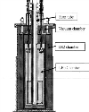
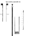
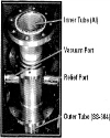
Top DESCRIPTION VECC ion trap sits inside a cold bore superconducting solenoid magnet of bore size 100 mm. The coil is immersed in a 100 liter liquid helium bath surrounded by a 250 liter liquid nitrogen jacket. The NMR probe with scanning arrangement, which goes into the cold bore has a diameter of around 70 mm, leaving an annular gap of 15 mm, where the vacuum jacketed scan tube would have to fit in. There is not enough space to provide a liquid nitrogen shield to reduce heat leak to helium. The length of the scan tube is 1.6 meter to position the NMR at the desired location. Outside wall of the scan tube will be in direct contact with the liquid helium. Inside temperature of the inner tube has to be maintained at around room temperature so that NMR probe can operate. Therefore the temperature gradient needs to be maintained is 20 K/mm. Figure-1 shows the scan tube position within the ion trap cryostat. |
Top DESIGN A 90 mm diameter SS-304 tube was chosen for the outer jacket of the scan tube. To minimize the heat leak to the liquid helium as well as to withstand the vacuum load and reduce welding distortion, the thickness is kept at 2 mm. The convection and radiation heat load was reduced by maintaining vacuum and putting ML! within the annular space. The optimum number of MLI and vacuum for the scan tube was approximated by the following equations1. |
1.Combined heat transfer in free molecule (Kn >10) and transition regimes |
σ = Stefan-Bolzman constant, |
Th= lower stack temperature of MLI, |
Tc= upper stack temperature of MLI, |
G=free molecular heat transfer function which is given by following equation |
αx= overall accommodation coefficient, β= ratio of specific heat, |
P= pressure measured at temperature T, |
϶ = fitting parameter (value 1.8 is used as per reference 1 since the conditions are similar) |
2. Combined heat transfer in continuum regime (Kn < 0.01) |
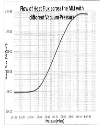
where Sm= distance between extreme layers Solving these equations, results are presented in the form of a comprehensive graph (see graph-1) for entire regime. |
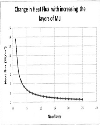
From the graph, it is observed that the vacuum better than 1CT4 mbar is sufficient to achieve the minimum heat load. Graph-2 shows that by adding numbers of MLI more than 15 would not reduce the radiation heat load significantly. |
The detailed thermal analysis was further carried out on this design using ANSYS to ensure that the inside temperature of the scan tube is maintained at around room temperature. An axi-symmetric model with PLANE 55 element was used. Temperature dependent material properties for thermal conductivity and specific heat were used. Initially keeping the thickness of the outer tube unaltered at 2mm, steady state calculations have been carried out for different materials and thicknesses of the inner tube and the results are shown in Table-1. |
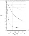
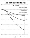
As the temperature at the bottom of the scan tube is 8°C, we cannot use it and it is difficult to provide any heater or air flow inside the scan tube. Therefore, transient analysis has been carried out for 12 hours out of which 8 hours is required for the measurement to complete. The results are plotted in graph-3. It is seen that some part of the inner tube still goes below the required temperature (20°C). |
Observing the temperature distribution along the length of inner and outer wall (fig.-2), it was thought to provide air flow at the outer top of the scan tube to maintain its temperature near the required value. |
An analysis with air flow at the top of the scan tube reveals that inside temperature would be at around the room temperature (graph-4) at the cost of increase of heat load to the liquid helium. |
The detailed results of the analysis with air flow (4m/s) are given in Table-2 and for all options the temperature is around room temperature. Therefore the aluminum tube was chosen for inner wall for light weight. |
Top FABRICATION & TESTING Fabrication includes machining, welding and multi-layer insulation wounding which have been done entirely in-house. During machining of 1.6 m long, 2 mm thick tube, several fixtures were employed. Several welding fixture were also used to avoid any distortion during welding (fig-3). Filler rod used for welding of SS304 tube is SS308 and for welding of aluminum rod is aluminum with 5% silicon. After welding and machining the permeability of nonmagnetic SS-304 rises. But above 0.25 T magnetic field, welded and machined SS-304 becomes increasingly nonmagnetic. |
15 layers of multilayer Super Insulation made of 6μm polyester foil with both side aluminized (400°A thick) are wound (fig-4) |
Fig-5 shows the top portion of the assembly. |
The cryo-shocking of the assembly with LN2was carried out three times. The vacuum leak test was carried out before and after the cryo-shocking test and the leak rate found in both the cases was less than 5×10⁻⁹ mbar.lit/s. |
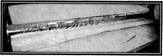
The inside temperature of the scan tube was measured after dipping into LN2. It was observed that after 15 hours the bottom temperature is 5°C and another testing was performed providing the air flow on the top of the scan tube and the temperature was maintained at 20°C even after 17 hrs of cooling. Fig-5 shows the set up during testing of the scan tube. |
The testing process was conducted with liquid nitrogen to reduce the cost and the results were verified with the analysis result obtained for liquid nitrogen. |
Top Figures | Figure-1:: Schematic view of the scan tube within the ion trap cryostat
|  | |
| | Graph-I:: Pressure in mbar vs heat flux in w/m2
|  | |
| | Graph-2:: Number of layers vs heat flux in w/m2
|  | |
| | Graph-3: shows temperature variation with time for without flow.
|  | |
| | Figure-2:: Temperature distribution along the length of the scan tube.
|  | |
| | Graph-3: temperature variation with time for different rate of air flow at the top of the scan tube.
|  | |
| | Fig-4:: Inner tube with Multilayer Super insulation
|  | |
| | Fig-5:: Top portion of thescan tube assembly.
|  | |
| | Figure-5: shows the scan tube during testing
|  | |
|
Tables | Table-1:: Steady state temp, for different options of inner tube
| | SI.No | Material | Thick | Temp.at Bottom | Temp. at Top | | 1 | Al | 3.33 mm | o°c | 0°C | | 2 | SS-304 | 3.33 mm | 6°C | o°c | | 3 | Al | 2 mm | 2°C | o°c | | 4 | SS-304 | 2 mm | 8°C | 1°C |
| | | Table-2:: Steady state temp, for different options of inner tube
| | SI.No | Material | Thick | Temp.at Bottom | Temp, at Top | | 1 | Al | 3.33 mm | 23°C | 22°C | | 2 | SS-304 | 3.33 mm | 24°C | 22°C | | 3 | Al | 2 mm | 24°C | 22°C | | 4 | SS-304 | 2 mm | 24°C | 22°C |
| |
| | |
|
|
|
|
║ Site map
║
Privacy Policy ║ Copyright ║ Terms & Conditions ║

|
|
|
751,598,904 visitor(s) since 30th May, 2005.
|
|
All rights reserved. Site designed and maintained by DIVA ENTERPRISES PVT. LTD..
|
|
Note: Please use Internet Explorer (6.0 or above). Some functionalities may not work in other browsers.
|