Cryogenic distribution system for ITER Proto-type Cryoline Test Bhattacharya R.1, Shah N.1, Badgujar S.1, Sarkar B.1 1ITER-India, Institute for Plasma Research, Bhat, Gandhinagar-382–428 (India) Abstract Design validation for ITER cryoline will be carried out by proto-type test on cryoline. The major objectives of the test will be to ensure the mechanical integrity, reliability, thermal stress and heat load as well as checking of assembly and fabrication procedures. The cryogenics system has to satisfy the functional operating scenario of the cryoline. Cryoplant, distribution box (DB) including liquid helium (LHe) tank constitute the cryogenic system for the test. Conceptual system architecture is proposed with a commercially available refrigerator/liquefier and custom designed DB housing cold compressor, cold circulator as well as phase separator with sub-merged heat exchanger. System level optimization, mainly with DB and LHe tank with options, has been studied to minimize the cold power required for the system. Aspen HYSYS® is used for the purpose of process simulation. The paper describes the system architecture and the optimized design as well as process simulation with associated results. Top |
INTRODUCTION ITER cryoline [1] has now in a phase of procurement stage for the early segment of entire cryolines, which will be supplied by Indian Domestic agency to ITER at Cadarache, France. Proto-type test of this cryoline (PTCL) [2] will be performed for the purpose of design validation as the design is complex in term of its functional parameters. The major objectives of the test will be to ensure the mechanical integrity, reliability, thermal stress and heat load as well as checking of assembly and fabrication procedures. The cryogenics system, required to perform the test, has to satisfy the functional operating scenario of the cryoline. The cryogenic system will supply supercritical helium (SHe) at 4.5 K and 3.7 K temperatures levels as well as liquid helium (LHe) with specific process conditions for different phases of test. All the required modes of operation establishment are also the responsibility of the cryogenics system proposed. Cryoplant, distribution box (DB) including LHe tank constitute the cryogenics system for the test. Conceptual system architecture is proposed with a commercially available refrigerator/liquefier having 1.0 kW at 4.5 K including 60 l/h capacity with modifications in the control system as per need. Custom designed distribution box houses cold compressor (CC), cold circulating pump (CCP) as well as phase separator with sub-merged heat exchanger. Distribution box, with custom made, plays an important role in optimizing the entire cryogenics system [3]. System architecture and internal configuration of components inside distribution box are considered to enhance overall performance. Aspen HYSYS® [4] is used for the detailed process simulation. |
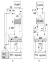
Top SYTEM CONFIGURATION Fig. 1(a) and (b) shows the overall layout of the two evaluated options of cryogenic system for the testing. Two analyzed schemes are different other in terms of components and interface point. |
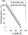
Cryoplant Cryoplant is commercially available cold box with the capacity of 1.0 kW equivalent at 4.5 K. This includes 60 l/h liquefaction capacity. This capacity is without liquid nitrogen (LN2) pre-cooling. LN2 pre-cooling stage is available in the cold box, which enhances the overall capacity. Control system of the ‘of-the-shelf cryoplant’ is actually customized to operate in line with the downstream system, testing requirements and operating modes. Fig. 2 shows cryoplant capacity considered for the analysis. It is also considered that refrigeration capacity can be increase by reducing liquefaction capacity as shown in Fig. 2. Scheme 1 In scheme 1 as shown in Fig. 1(a), DB is connected with cryoplant. LHe tank and PTCL/Application are connected at the downstream side of DB. CC with an inlet heat exchanger (Hx) enhances quality of liquid fraction after the Joule-Thomson (JT) valve to DB bath. CCP operates in closed loop having CCP outlet heat exchanger sub-merged at DB bath depositing part of heat load of CCP. PTCL heat load with remaining part of CCP load are deposited at DB bath with second heat exchanger, which ensures stable temperature inlet in CCP. LHe tank is required to boost the capacity of the cryoplant during 3.7 K testing operation. Scheme 2 LHe tank is directly connected to the cryoplant in case of scheme 2. DB is connected at the downstream of LHe tank, but, CC return mass flow goes to the cryoplant return along with LHe tank return flow as shown inFig. 1(b). Both sub-merged heat exchanger are located at the DB bath dumping heat load from PTCL and CCP. PTCL is connected with downstream side of DB. Top OPERATING CONDITION PTCL or application load is considered as 400 W at 4.5 K maximum for the cryogenics system design, whereas, 300 W equivalent at 3.7 K is considered as maximum heat load. Cryogenics system provides SHe flow up to 600 g/s at 4.5 K, 0.4 MPa and 3.7 K, 0.4 MPa to PTCL as per experimental need. It also supplies LHe during heat load measurement of PTCL. It is assumed that discharge temperature of the cryoplant is 5.0 K and 5.1 K after last stage heat exchanger of cold box before isenthalpic expansion at JT valves during 4.5 K and 3.7 K respective SHe flow to PTCL. LHe level of LHe tank should be within 20 % to 80 % for both schemes. LHe level of DB bath must be above 30 % in order to ensure that heat exchangers are fully submerged in LHe for the highest effectiveness. Pressure drop offered by PTCL is almost constant during SHe flow condition at 4.5 K and 3.7 K. Gross 140 W heat load is considered from DB, LHe tank and connecting cryolines. |
Top RESULTS Simulations for scheme 1 and 2 have been carried out. Steady-state and optimized operation results are discussed. This is required to conclude the selection of the scheme for the cryogenics system |
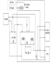
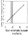
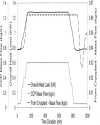
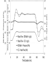
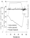
Steady-state Results In order to compare two proposed schemes, operating point at 500 g/s SHe operation at 3.7 K is considered resulting heat load of 650.6 W to be deposited at DB bath in each scheme. Table 1 shows comparative result during this condition. Where, ṁ = Total mass flow from cryoplant, T1 = Supply temperature from cryoplant, T2 = Overall cryoplant return temperature, Qcc = CC power. From Table 1, it is evident that scheme 1 is not preferable as it consumes more power for CC operation and overall cryoplant return temperature is higher than that 5.1 K supply temperature. This causes unstable condition at the last stage heat exchanger inside cryoplant. Scheme 1 also needs one more heat exchanger at the suction side of CC. Hence, scheme 2 is selected over scheme 1. Table 2 shows results of CCP and CC considering scheme 2. Detailed process flow diagram (PFD) of scheme 2 is shown in Fig. 3. Results of Optimized Operation From the steady state result of selected scheme 2, it can be shown that during 600 g/s at 4.5 K SHe operation, total heat load on cryoplant is 861.5 W, which is within the capacity limit of the cryoplant. Hence, stable operation of cryoplant is feasible. Whereas, in case of 3.7 K operation, DB bath is evacuated up to 59.35 kPa using CC to achieve 3.7 K temperature. During 600 g/s at 3.7 K, available refrigeration capacity is not sufficient. LHe tank supports the capacity boost for a limited period of time. Hence, dynamic simulation has been carried out with CCP mass flow varying from 50 g/s to 600 g/s for scheme 2. Fig. 4 shows the volume of LHe tank needed for the various experimental availability at 600 g/s, 3.7 K SHe. Minimum 1.5 m3 volume for LHe tank is required to run CC for 15 hours continuously. Scheme 2 has been evaluated further for internal components responses/behaviors of DB. In this case, CCP mass flow is increased from 50 g/s to 600 g/s at 3.7 K at an average rate of 0.1 g/s/s. Then, CCP has been operated in stable condition for next 10 hours at 600 g/s. CCP mass flow is reduced back to 50 g/s. During this entire process, return temperature back to cryoplant is maintained below or around 5.0 K to ensure stableoperation of cryoplant. Observed responses/behaviors are shown in Fig. 5, 6 and 7. Fig. 5 specifically shows overall heat load variation on cryoplant with peak value of 1.28 kW. Mass flow supply from cryoplant is saturated at 62 g/s as per its capacity. Additional heat load is compensated by utilizing LHe tank reserve capacity for a stable operation. Fig. 6 shows response of CC and DB bath. DB bath inlet mass flow demand is increased along with increase of heat load at DB bath. CC mass flow rate is also increased due to higher amount of LHe vaporization to maintain DB bath pressure around 60 kPa. This ensures stable temperature at DB bath at 3.7 K with a higher heat load from CC to cryoplant. Fig. 7 shows dedicated temperature control scheme of combined return mass flow from DB and LHe tank back to cryoplant low pressure side. Due to the peak heat load from CC as shown in Fig.6, return temperature of helium from DB is higher than 5.0 K. LHe tank is equipped with a sub-merged electrical heater. This heater at LHe tank is employed to create additional cold helium gas at 4.5 K, which is mixed with return mass flow from DB back to cryoplant to control overall return temperature below or around 5.0 K. Fig. 7 shows a stable return temperature around 5.0 K using electrical power. This additional electrical power is termed as ‘Heat-to-Control’, which is added to the heat load budget. LHe tank plays dual role of capacity boost up and temperature control, which leads to a steady decrease in LHe level as shown in Fig. 7. Top CONCLUSION Conceptual design of the cryogenic system architecture is performed. Industrially available cryoplant is considered for the faster on-site implementation. Distribution box is conceptualized as per experimental need with two options. Scheme 2 is selected with a cost saving as ‘inlet heat exchanger’ of CC is not required. ‘Peak mass flow’ operation of CCP is established specially for 3.7 K operation for limited period of time. ‘Heat-to-Control’ must be considered at design stage to calculate ‘overall heat load’ budget of cryogenic system. All requirements of the system are fulfilled and supported by process analysis. |
Top ACKNOWLEDGEMENT The authors would like to thank the Project Director, ITER-India, IPR for his support, encouragement and suggestion during the execution of the work. This work has been carried out as a part of ITER-India responsibilities as participant team in ITER. The views and the opinion expressed herein do not necessarily express those of the ITER organization and the ITER partners. |
Top Figures | Fig. 1.: (a) Scheme 1 and (b) Scheme 2
|  | |
| | Fig. 2: Refrigeration Vs Liquefaction capacity of cryoplant
|  | |
| | Fig. 3.: PFD of scheme 2
|  | |
| | Fig. 4.: LHe tank storage requirement
|  | |
| | Fig. 5.: Cryogenic system response during CCP mass flow variation from 50 g/s to 600 g/s
|  | |
| | Fig. 6.: CC and DB bath response
|  | |
| | Fig. 7.: Temperature control of combined return mass flow from DB and LHe tank to Cryoplat
|  | |
|
Tables | Table 1: Scheme 1 and 2 comparison
| | T1(K) | ṁ(g/s) | T2(K) | Qcc(W) | | Scheme 1 | 5.1 | 60.6 | 5.5 | 331.9 | | Scheme 2 | 5.1 | 60.6 | 4.97 | 265.6 |
| | | Table 2: CCP and CC parameters
| | Parameter | CCP | | CC | | Max. Mass flow (g/s) | 600 | | 37.33 | | Pressure rise or ratio | 50 kPa | | 2.19 | | Adiabatic efficiency | 0.7 | | 0.7 | | SHe Temperature | At 4.5 K | At 3.7 K | | | Max. Power (W) | 321.5 | 300.7 | 285.6 |
| |
|