
|
|
|
(3.137.218.220)
|
|
Users online: 3556
|
|

|
|
|
|
|
Ijournet
|
|
|
|
|
|
|
Static and dynamic behavior of cryogenically cooled hydrostatic journal bearings for space applications Kumar Mukesh1, Nandi T.K.2 1Cryogenic Engineer Centre, IIT Kharagpur-721302 2Cryogenic Engineer Centre, IIT Kharagpur-721302 Abstract Externally pressurized cryogenically cooled (using LOX or LH2 as coolant) hydrostatic bearings are being considered as an alternative to the conventional ball bearing system of a cryogenic rocket engine turbopump. Comparing with ball bearing system, hydrostatic journal bearings (HJBs) offer several advantages like, higher load capacity, higher stiffness with low coefficient of friction, good damping characteristic and vibration stability. Because of very low viscosity of cryogenic liquids, compared with oil (as lubricant), modeling of cryogenic HJBs, is complicated by factors like: turbulent fluid film, inertia effect, compressibility and variation of cryogenic liquid properties. In this paper a finite difference based numerical model is presented for prediction of static and dynamic performances of LOX/LH2 lubricated hydrostatic journal bearings. Pressure distribution in the fluid film is obtained by solving relevant Reynolds equation. Dynamic behavior is studied through the determination of stiffness and damping coefficients by using finite disturbance method. Sample results have been presented both for static and dynamic conditions. Top Keywords Hydrostatic bearing, Numerical modeling, Static and dynamic study. Top | INTRODUCTION Conventional ball bearing system of a cryogenic rocket engine turbopump has limitation on its maximum rotational speed. This leads to inefficient operation of turbines and pumps. A possible solution of this problem is the replacement of ball bearings by LH2/LOX lubricated hydrostatic journal bearings (HJBs). Unlike ball bearings, hydrostatic journal bearings do not have any operating speed limitation. In addition, they offer low frictional loss, high load capacity and stability. Moreover, the cryogenic propellants which are delivered at a high pressure by the main pumps can be used as bearing coolant. However, the difficulties in using cryogenic propellants (LOX/LH2) as bearing coolant are due to their low temperature, low viscosity, slight compressibility and with their nonavailability at start-stop transients. |
Several theoretical works in hydrostatic bearing with turbulent film are availsble in literature. Braun et.al. [1] presented an integrated analysis of the behavior of two rows, 20 staggered pockets cryogenic HJBs. Andres [2] presented a HJB design for SSME high pressure oxidizer turbopump with hydrostatic annular seals. In another work, Andres [3] developed a barotropic fluid model for a LH2 cooled HJB. Yoshikawa et.al. [4] studied dynamic characteristics of cryogenic HJB with two rows staggered recess. Redcliff and Vohr [5] developed an analysis to predict bearing at steady state and transient conditions. Leonard and Rowe [6] experimentally observed whirl instability beyond a critical rotational speed. Hannum and Nielsen [7] have carried out experimental work on high speed low life LH2 hybrid bearing for reusable rocket engine turbomachinery. |
An appropriate model for cryogenic HJBs should consider turbulent fluid film, inertia effect at the recess edges and property variations. In this paper a numerical model is presented which considers these aspects. |
Top NUMERICAL MODEL The working principle of hydrostatic bearing is well described in text books. Load capacity of the bearing is usually estimated from the pressure distribution in the bearing film. The pressure distribution is obtained by solving Reynolds’ equation given as |
where Gx and Gz are turbulent coefficients and are calculated from [8], |
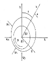
Using the coordinate system shown in Fig. 1, the film thickness is expressed as |
| in Eq.(1) can now be written as |
Following boundary conditions are applied to solve Reynolds’ equation |
Pressure drop at the recess edges occurs due to acceleration in the fluid. The increase in fluid velocity is compensated by decrease in fluid pressure across edge. |
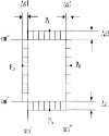
Solution of Reynolds’ equation requires the value of recess pressures. In order to find recess pressures, initially a set of recess pressure is assumed. Based on these recess pressures, pressure distribution, in the film is determined by solving Reynolds’ equation. Now the flow of coolant from each recess (Eq.10, Fig. 2) is equated to the flow through the orifice (Eq.11), so that a new set of recess pressure is obtained. Further assumptions for the first iteration are GX=GZ=1/12 and the recess edge pressure same as the recess pressure. Iterations continue till the convergence in each recess pressure is obtained. |
Once the fluid film pressure distribution is available, the static performance parameters such as radial load capacity, flow rate pumping power and frictional power loss etc. can be calculated from the standard equations available in literatures. |
Top DYNAMIC COEFFICIENTS From rotordynamic point of view, dynamic behavior of a journal bearing is studied by finding stiffness and damping coefficients. Following relationships are used for obtaining dynamic coefficients through computation of force, displacement and velocity for incremental motion about a static equilibrium position: |
Using finite disturbance technique [9], stiffness and damping coefficient are calculated from |
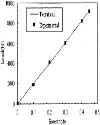
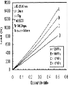
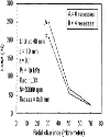
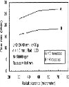
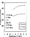
Top RESULTS AND DISCUSSIONS Fig.s 3-4 compare the predicted data with the experimental [10] data. Excellent matching is observed for load capacity. Fig. 4 shows that theoretical predictions for coolant flow rate are about 10–12% higher than the experimental data. Variations of load capacity with eccentricity ratio and radial clearance are shown in Fig.s 5 and 6. Load capacity increases with eccentricity ratio and decreases with radial clearance. |
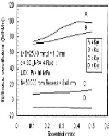
Fig.s 78, 9, to 10 show the variations of flow rate and pumping power. Flow rate as well as pumping power decreases marginally with eccentricity ratio. However, for a given eccentricity ratio flow increases significantly with increasing supply pressure. |
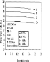
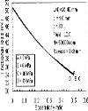
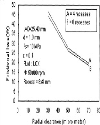
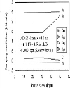
Fig.s 11 and 12 present the variation of frictional loss with eccentricity ratio, radial clearance, supply pressure etc. While frictional losses decrease significantly with eccentricity ratio (for a given supply pressure), negligible change in frictional loss is observed with supply pressure. |
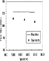
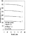
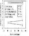
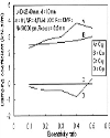
Fig.s 13- 14, 15, 16 present the variation of dynamic coefficients with operating parameter such as eccentricity ratio and rotational speed. |
The cross coupled stiffness coefficients (Kxyand-Kyx) are approximately one order of magnitude lower than the direct stiffness coefficient because of low viscosity. Negative cross coupled stiffness coefficient enhances the stability by contributing a force that opposes the fluid motion in the direction of rotor. But negative value of cross coupled stiffness coefficient beyond a certain range suggests the possibility of whirl in that region of operation. The values of cross coupled damping coefficients are usually very small in comparison to direct damping coefficients and may not have significant effect on the stability of the bearing. The dynamic coefficients are almost invariable for eccentricity ratios 0.1 to 0.5. Usually dynamically loaded hydrostatic journal bearing is designed for maximum damping coefficients. |
Top CONCLUSIONS In this paper a numerical model for performance prediction of a cryogenically cooled hydrostatic journal bearing is presented. Parametric results are obtained both for static and dynamic conditions. |
Top NOMENCLATURE ACKNOWLEDGENT The authors thankfully acknowledge Indian Space Research Organization for financially supporting this work. |
Top Figures | Fig. 1: Coordinate system
|  | |
| | Fig. 2.: Nomenclature around a recess for computing net flow to the recess
|  | |
| | Fig. 3: Comparison of load capacity for theoretical and experimental results [10]
|  | |
| | Fig. 4: Comparison of flow rate for theoretical and experimental results [10]
|  | |
| | Fig. 5: Variation of load capacity with eccentricity ratio and supply pressures
|  | |
| | Fig. 6: Variation of load capacity with radial clearance and number of recesses
|  | |
| | Fig. 7: Variation of flow rate with eccentricity ratio for varying supply pressures
|  | |
| | Fig. 8: Variation of pumping power with eccentricity ratio and supply pressure
|  | |
| | Fig. 9: Variation of flow rate with radial clearance for and number of recesses
|  | |
| | Fig. 10: Variation of pumping power with radial clearance and number of recess
|  | |
| | Fig. 11: Variation of frictional loss with eccentricity ratio and supply pressure
|  | |
| | Fig. 12: Variation of frictional loss with radial clearance and number of recesses
|  | |
| | Fig. 13: Variation of stiffness coefficient with eccentricity ratio
|  | |
| | Fig. 14: Variation of stiffness coefficient with journal speed
|  | |
| | Fig. 15: Variation of damping coefficient with eccentricity ratio
|  | |
| | Fig. 16: Variation of damping coefficient with journal speed
|  | |
|
Table :
| | C = damping coefficient | | C = radial clearance | | p = fluid pressure | | Cd = discharge coefficient | | e = eccentricity | | h = film thickness | | K = stiffness coefficient | | p = dynamic viscosity | | Q = coolant flow rate | | R = radius of journal | | d = orifice diameter | | Uc = circumfer. velocity | | ɸ = attitude angle |
| |
| | |
|
|
|
|
║ Site map
║
Privacy Policy ║ Copyright ║ Terms & Conditions ║

|
|
|
751,580,156 visitor(s) since 30th May, 2005.
|
|
All rights reserved. Site designed and maintained by DIVA ENTERPRISES PVT. LTD..
|
|
Note: Please use Internet Explorer (6.0 or above). Some functionalities may not work in other browsers.
|