INTRODUCTION A new liquefier of Air Liquide, France make Helial 2000 has been procured and installed in VECC in order to add redundancy to the cryogenic system and to cater higher cryogenic load requirement which arises from new projects [1]. This liquefier has been installed in parallel with the existing liquefier Helial 50 in such a way that any one of the two liquefiers can be connected to the cyclotron cryogenic loads as and when required. During installation and commissioning of this liquefier a number of problems were faced. |
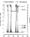
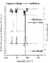
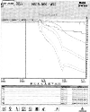
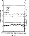
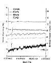
Space Constraints for Nstallation nearer to the existing liquefier. As there was not enough space, it was extremely difficult to existing cryogenic lines, length of superinsulated vacuum transfer lines should be accurate or adjustable by few cm. The cryo-lines were made flexible by keeping some degree of rotational movement in the bayonet coupling of the existing and new transfer lines. Irrespective of this arrangement, GHe supply line from Helial 50 to the valve box could not be accommodated and, therefore, in situ modification, testing etc. was made. Flange Connections of Pipelines From previous experiences with the old liquefier Helial 50, we found that any major work inside the cold box requires the cutting and rewelding of the HP and LP pipelines. To get rid of these issues, flanged connections are made for this liquefier. All the metal pipelines have been extensively cleaned by pressurization and depressurization technique in order to ensure absence of any metal chips. Failures of Components and Their Rectification All the control interfacing with field instruments was done by VECC and, therefore, their electrical integrity was tested initially. Some connections inside the control panel of the cold box were found wrong and hence, rectified. Pressure safety valves of the dewar blew off at the pressure lower than that set by the manufacturer. At its first run, the cycle compressor generated abnormal noise which was created due to the mechanical friction of the screws of the compressor. The compressor screw was replaced with a new one and it has been running fine now. The reading from the moisture analyzer made by GE sensing and supplied with the cold box was not tallying with our moisture analyzer and Linde Impurity analyzer. It was not allowing the start of cool down process through the turboexpander. It was replaced twice and finally rectified with Michelle Instruments make one. The level transmitter for monitoring Dewar level was also damaged at the time of cool down and the cool down was forced to stop till it was replaced. Level transmitter was replaced with a new one. One temperature switch of the heater for drying failed and spares have been asked for. All the temperature sensors inside the cold box are of Cernox type because they have been proven very stable over repeated thermal cycling and under extended exposure to ionizing radiation and they have negligible magneto-resistance at low temperatures. LN2 precooling heat exchanger temperature sensor failed only for few thermal cycles and forced us to connect a CLTS (Cryogenic Linear Temperature Sensor), which was put as a spare. Cernox sensors having a negative temperature coefficient and non-linear characteristics (tens of at 300K to few k at 4.2K) demand variable current source at different temperature ranges in order to keep the resulting measured voltage between 1 mV and 15 mV. This enables higher resolution at higher temperature range and less heat ingress to the cryogen due to Joule heating. Therefore, normal RTD transmitter having 10A excitation supplied with the cold box is not capable of representing the best possible resolution at higher temperature. Erformance Tests The performance test of the new liquefier was conducted and it achieved refrigeration capacity of 340 W at 4.5K as shown in Figure 2 and liquefaction capacity 64 lit/hr as shown in Figure 3. The guaranteed refrigeration and liquefaction capacities of Helial 2000 are 415 W at 4.5K and 85 l/hr respectively. A number of investigations was carried out and found that the only possibility is the limitation of helium flow through the cold box resulting in lower performance. Keeping this in mind, the plug change in the JT valves, return valves were suggested, which was implemented by the supplier. Final acceptance test for performance is yet to be carried out. Pressure Control Loop Flow generated by parallel run of two compressors is around 100 g/sec and flow requirement by the cold box is 85 g/sec. The excess flow was managed by the bypass valve. One compressor is powered by an UPS and other one is fed from normal power. Due to dip or power failure one compressor stops and in effect its high pressure gas is fed to the low pressure section. This increases the pressure in LP side which in turn increases the pressure in HP side. The pressure fluctuation generally shuts the turbine and consequently, the cold box. This can be avoided by opening the unloading valve in case of a certain rise in pressure in HP section above the set point, as suggested by VECC. The above has been implemented where the opening is based on the buffer pressure as shown in figure 7. Figure 6 shows the corresponding opening of PCV289 which varies with the buffer pressure. Expander Control with Attenuators The attenuators are the parameters selected depending on the different process parameters which may be detrimental to the turbine health. When some of the parameters cross the limit safe for the turbo-expander, the inlet valve opening of the turbo-expander is restricted using the attenuator values. The cryogenic refrigeration loads are controlled by level attenuator and heater power. A balance has been made between the two keeping in mind the operating pressure in the cryostat. Cool Down of the Cryogenic System and Related Changes in the Control The cool down of the whole system was performed twice: From 300K down to 120K in Cryostat between June 29, 2010 and July 10, 2010. Cool down was stopped on July 10th after massive pollution on the system during Kaeser compressor leak tests using dry air. The contamination of helium was occurred due air leak through a solenoid valve as it is not leak tight in reverse direction and was identified by insufficient cooling of the turbo-expander due to decrease in flow. 2-From 120K down to 4K in Cryostat between July 19, 2010 and July 23,2010.
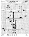
During the cool down process the main requirement from the cryostat side is that the temperature difference between the outlet and inlet temperature should be below 100K. This can be achieved by controlling the cooling power of the turbine from the feedback temperatures either directly from the cryostat or from the inlet JT temperature and cryostat return temperature in the cold box. The later one is implemented as it is important to keep the temperature differential below 50K across the JT Heat Exchanger also. A new attenuator is proposed and implemented depending on the temperature difference across the JT heat exchanger. Initially subcooler liquid helium level control was proposed with a level control valve LCV707 which takes a smali amount of flow from the main liquid line. It was tested below 80% and did not work satisfactorily. Decision was taken to use FCV703 (Cryostat filling line) for Helial 2000 and FCV706 for Helail 50. Two additional controllers were implemented on those valves in the Valve Box to regulate the Level LT701 in the sub-cooler. Performance Related to Number of Compressors Initially the cold box of Helial 2000 was operating with two compressors. A test was made to operate the cold box with one compressor for the refrigeration and liquefaction loads as indicated in figure 10 In this condition the helium flow requirement was sufficient to cater cryogenic load, i.e., the flow requirement is less than 50g/s with 50% opening of FCV450 and 26% opening of the JT valve. The extra flow is managed by the bypass valve present in the ORS in case of two compressors. Figures 10a and 10b show the performance of Helial 2000 with one and two compressors respectively. Here refrigeration load for magnet currents at Alpha Current = 440 A and Beta Current = 270 A and liquefaction Load for current lead flow totally 0.053 g/sec which is equivalent to 1.51 lit/hr LHe at 4.2K is represented. Performances of Heiial 2000 with different Refrigeration Loads Performance of Helial 2000 at different load conditions of the cryostat is shown in Table 1. ATLT is the attenuator applied to the turbine speed to limit the cooling capacity of the liquefier and is dependent on the Dewar LHe level. The release of ATLT (Dewar Level Attenuator) means increase in the refrigeration power as evident from second and third rows of table 1. Liquefaction load is due to the total current lead flow and constant for the last four conditions at 0.06 g/s (equivalent to 1.73 l/hr). At alpha current of 2 A and beta current of 42 A, which will contribute to refrigeration load, the heater power added to the Dewar will increase to 102.0 W. At alpha current of 515 A and beta current of 420 A, the heater power added to the dewar is 30.7 W, therefore, the increase in magnet current contributes to 71.3 W refrigeration load at 4.5 K at the same ATLT. A remarkable change in vacuum level of the Cryostat Outer Vacuum Chamber (OVC) is observed as a new vacuum pump was added to the chamber. There is a significant change in refrigeration power with change in vacuum level of OVC as observed in first and third rows of Table 1. Top CONCLUSION The performance test in isolated condition has already been done in October 2010. The refrigeration test has been carried out by isolating the cryostat and putting heater load in the Dewar. The reported refrigeration load was around 325 W at 4.5K. The pressure drop of 250 mbar, ten times the usual value, was observed across the first two exchanger HP line, which indicated choking in the first two heat exchangers due to impurities. After full warming, conditioning of the HP line of the cold box was executed. |
Top ACKNOWLEDGEMENT I sincerely thank to Shri Anupam Mandal, Shri Ananda Das and Shri Ranjan Kar for their earnest contribution to make the whole system operational. I must acknowledge the continuous support and encouragement from Dr. R.K. Bhandari, Director, VECC. |
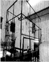
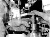
Top Figures | Figure 1.: Location of Cold Box on a platform and Dewar and cold box on the ECR bay below.
|  | |
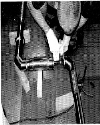
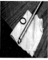
| | Figure 2.: Repairing of the coaxial transfer line for GHe Supply.
|  | |
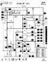
| | Figure 3.: Screen shot showing the refrigeration capacity on 16/05/2010
|  | |
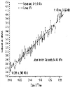
| | Figure 4.: Liquefaction test result of Helial 2000 between 9:00 AM to 11:00 AM on 19/05/2010
|  | |
| | Figure 5a.: Gas return line valve plugs after & before changing from left
| 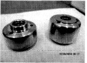 | |
| | Figure 5b.: JT valve plugs before & after changing from left
| 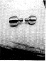 | |
| | Figure 5c.: Photograph showing the image of the cryogenic valve stem
|  | |
| | Figure 5d.: Actuator location of the cryogenic valve
|  | |
| | Figure 6.: The fluctuation in opening of PCV289 to accommodate excess gas due to stopping of one compressor and that of PCV280 at the time of its start
|  | |
| | Figure 7.: Buffer, LP and HP pressure curves before arid after implementation of the proposed control scheme based on HP and buffer pressure.
|  | |
| | Figure 8.: Cool-down curve which started on June 29th 2010
|  | |
| | Figure 9.: SCADA of valve Box after implementation of two control loops for level
|  | |
| | Figure 10a.: Operation of the liquefier with single compressor
|  | |
| | Figure 10b.: Operation of the liquefier with dual compressor
|  | |
|
Table | Table 1: Helial 2000 Performance during the different load conditions of the cryostat
| | No.Go mp | Alpha Current(A) | Beta Current(A) | Cryostat OVC(mbar) | Liquefaction load as lead flow (l/hr) | ATLT | Speed (rps) | Heater Power (W); | Dewar Level (Lit & %) | | Warm Turbine | Cold Turbine | | 2 | 440 | 270 | 8.1×10⁻⁶ | 1.51 | 0.86 | 2510 | 1570 | 33.6 | 190 & 22 | | 2 | 515 | ! 420 | 4.8×10⁻⁶ | 1.73 | 0.88 | 2583 | 1817 | 30.7 | 202 & 23 | | 2 | 515 | I 420 | 4.3×10⁻⁶ | 1.73 | 0.91 | 2667 | 1720 | 84.2 | 178 & 21 | | 2 | 2 | ! 42 | 5.8×10⁻⁶ | 1,73 | 0,88 | 2589 | 1696 | 102.0 | 196 & 22.4 | | 2 | 455 | ! 311 | 1.5×10⁻⁶ | 1,73 | 0.89 | 2616 | 1679 | ; 93.8 | 175 & 21 |
| |
|