Design approach of seismic interface for cryoline with tokamak building for ITER Badgujar S.1, Sarkar B.1, Vaghela H.1, Shah N.1, Naik H. B.2 1ITER-India, Institute for Plasma Research, Bhat, Gandhinagar-382428, India 2Sardar Vallabhbhai National Institute of Technology, Surat-395007, India Abstract ITER Tokamak building is designed with seismic isolation pads lo protect the Tokamak components from seismic events. Two main cryolines, designated as ciyolines between buildings (Mg & CP), runs from interconnection box in cryoplant building to the Tokamak building. The lines outside Tokamak building are supported by seismically non-isolated supports. The cryoline design at the interface between seismically isolated and nonisolated support systems needs to be studied to fulfill the functional requirements. One of the options for interface, universal expansion joint has been modeled in CATIA with actual thickness of each ply and inter-ply distance, analyzed in ANSYS using contact definition, as a part of the preliminary study. The bellows have been checked by design calculation as per EJMA standard for the specified movements. The paper will present approach for conceptual design of interface, problem definition & boundary conditions, methodology for analysis and preliminary results of stress pattern for expansion joints. Top Keywords ITER, Tokamak, Cryoline, Seismic, Multi-ply bellows, CATIA, ANSYS. Top |
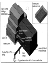
INTRODUCTION ITER will be the first tokamak bedded on a soft pillow. To reduce the seismic loads on the tokamak building and the internal equipment, the full tokamak complex is sitting on seismic pads that considerably reduce the horizontal seismic excitation during seismic events [1]. In order to assure safe operations at all times, ITER will be placed on approximately 560 isolation pads made of elastomer, an elastic polymer and steel. Figure 1 show the tokamak building placed on the isolation pads. At ITER the distribution of cryogens is made via a complex network of multi-process pipe cryolines and cryo-distribution system [2], The system of cryolines transport cooling power from the cryoplant building, where the liquid helium refrigerators are installed, to the different users, mainly superconducting magnets and cryo-pumps. Two main cryoline designated as cryolines between buildings (‘Mg’ & ‘CP’), run from the cryoplant termination cold box in cryoplant building to Tokamak building. The cryolines—‘Mg’—& ‘CP’ outside Tokamak building are supported by seismically nonisolated supports taken from assembly hall. The layout of cryoline ‘Mg’ on the plant bridge and representative location of the seismic interface near the tokamak building is shown in Figure 1. The design for these cryolines at interface between seismically isolated and non-isolated support system is studied to fulfill the functional requirements; to be able to sustain seismic events without breaking. The expected displacements during seismic events are ± 40 mm in the horizontal direction and ± 3 mm in the vertical direction. The study has been carried out for cryoline ‘Mg’ also refereed as ‘MAG CL’ [3]. |
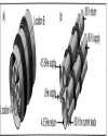
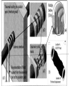
Top DESIGN DESCRIPTION Cryoline Prior to defining the seismic interface, preliminary studies for thermal, structural and hydraulics have been carried out for the cryoline. The study has been carried out for cryoline, with six process pipes sizes ranging from 100 to 300 mm, fixed supports, sliding supports assembled inside the thermal shield and outer vacuum jacket approximately 1000 mm. Cryoline has been divided in to straight and elbow section to match the isometrics of line. The cryoline is 126 meter long with total 17 sections of six different types. The penetration of the tokamak building, which is passage for cryoline to the plant bridge, is considered as fixed point. Seismic interface The cryoline has interface between seismically isolated and non-isolated support system. Few possible options, namely, use of universal expansion joints, flexible hoses alone, combination of bellows & hoses, double-hinge articulated bellows system can be considered for the interface. The option with universal expansion joints (multi-ply bellows) has been studied in detail. The universal expansion joints have been selected for each process pipe as well as outer vacuum jacket (OVJ) for ± 40 mm axial as well as lateral movement. The details of the selected expansion joints [4] are summarized in the Table 1. It has been checked by design calculation as per EJMA [5] that the selected expansion joint worked for the specified movements. It has been found from the calculation that all the stresses are within limit. The results are summarized in Table 2. The options of using flexible hoses alone and in combination with bellows are being studied. Modeling of multi-ply bellows in CATIA The multi-ply bellows in each process pipes as well as OVJ have been modeled in CATIA® Version 5.16 [6] software with actual thickness of each ply and assumed inter-ply distance. The multiply bellow has been modeled so that the interaction between different ply as part of load transfer can be taken using contact definition during the analysis. While modeling the bellows, interplay distance of 0.15 mm has been kept, whereas in actual bellows there is negligible distance between two plies. Figure 2(a) and (b) shows the CATIA model of expansion joint for OVJ and internal process pipes respectively. Figure 3 (a1 to a3) shows the representative view of the seismic interface in situ along with the wall of the tokamak building. Figure 3 (a4) shows the zoom view of plies and connection of plies to the collar. Top ANALYSIS METHODOLOGY The finite element (FE) analysis has been carried out using ANSYS© 10.0 [7], The structural analysis considering the pressure, temperature as well as gravity loads is performed to estimate the stress based on the applied boundary conditions. The temperature dependent material properties of AISI 304L have been used for carrying out the structural analysis. The analysis is carried out in two steps. In first step the contact between the two plies of the expansion joint was not considered. The analysis has been carried out for all the selected expansion joints (process pipes as well as OVJ). In the second step, the interaction between the plies as a part of load transfer has been considered by using contact definition in the analysis. The analysis has been carried out only for 4.5 K SHe return pipe. |
FE model without contact Finite element mesh generating software, Hypermesh ® [8], has been used to prepare the meshed model. Mid-surfaces have been extracted from the solid model imported from CATIA and used for meshing in Hypermesh. Elements SHELL 63 and SOLID45 are used in the meshing. Shell element is used for bellows and pipes whereas solid element is used for the collar. At the solid-shell interface, two shell elements with minimal thickness of 0.1 mm are extended into solid faces to connect the shellwith solid elements. The number of nodes Ielemenls used in the analysis for ON 100,200, 300, and 1000 (refer Table 1) are109600/102080, 305200 I 290400, 239200/224400 and 266240/244608 respectively.The element checks have been performed in Hypermesh before proceeding for the analysis. Modeling of multi-ply bellows in CATIA The multi-ply bellows in each process pipes as well as OVJ have been modeled in CATIA® Version 5.16 [6] software with actual thickness of each ply and assumed inter-ply distance. The multiply bellow has been modeled so that the interaction between different ply as part of load transfer can be taken using contact definition during the analysis. While modeling the bellows, interplay distance of 0.15 mm has been kept, whereas in actual bellows there is negligible distance between two plies. Figure 2 and (b) shows the CATIA model of expansion joint for OVJ and internal process pipes respectively. Figure 3 (a1 to a3) shows the representative view of the seismic interface in situ along with the wall of the tokamak building. Figure 3 (a4) shows the zoom view of plies and connection of plies to the collar. Top ANALYSIS METHODOLOGY The finite element (FE) analysis has been carried out using ANSYS© 10.0 [7], The structural analysis considering the pressure, temperature as well as gravity loads is performed to estimate the stress based on the applied boundary conditions. The temperature dependent material properties of AISI 304L have been used for carrying out the structural analysis. The analysis is carried out in two steps. In first step the contact between the two plies of the expansion joint was not considered. The analysis has been carried out for all the selected expansion joints (process pipes as well as OVJ). In the second step, the interaction between the plies as a part of load transfer has been considered by using contact definition in the analysis. The analysis has been carried out only for 4.5 K SHe return pipe. |
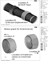
FE model without contact Finite element mesh generating software, Hypermesh ® [8], has been used to prepare the meshed model. Mid-surfaces have been extracted from the solid model imported from CATIA and used for meshing in Hypermesh. Elements SHELL 63 and SOLID45 are used in the meshing. Shell element is used for bellows and pipes whereas solid element is used for the collar. At the solid-shell interface, two shell elements with minimal thickness of 0.1 mm are extended into solid faces to connect the shellwith solid elements. The number of nodes Ielemenls used in the analysis for ON 100,200, 300, and 1000 (refer Table 1) are109600/102080, 305200 I 290400, 239200/224400 and 266240/244608 respectively.The element checks have been performed in Hypermesh before proceeding for the analysis. FE model with contact The 4.5 K SHe return pipe (DN 300) has been modeled with 153200 number of elements and 127200 number of contact elements. Automatic surface to surface contact has been defined between the two plies. Similar contacts have been defined for each set of adjacent plies. Total number of such contacts is 6 for 4.5 K SHe return pipe. Automatic single surface contact has been defined for each ply. This has been defined to avoid self penetration of the ply. Similar contacts have been defined for each ply. Total number of such contacts is 8 for 4.5 K SHe return pipe. Figure 3(b) shows the meshed geometry used for the analysis of 4.5 K SHe return pipe. Boundary conditions The analysis has been carried out with the applied boundary conditions. The circumferential nodes at the location A, shown in Figure 2, are constrained fully (fixed in all degrees of freedom). The circumferential nodes at the location B, shown in Figure 2, are subjected to a displacement of 40 mm in X, Y direction and 3 mm in Z direction. The pressures and temperatures are applied on the expansion joint as summarized in Table 3, along with standard earth gravity in Z direction. Figure 3(b) shows the enforced displacements at the location B and fixing of the nodes at location A. obtained from the analysis and the stresses estimated by the design calculation as per EJMA is a matter of further discussion. Top CONCLUSIONS A preliminary conceptual design of the seismic interface for cryoline ‘Mg’ has been presented in this paper. The universal expansion joints were selected and checked as per EJMA for the specified movements. The option of using flexible hoses alone and in combination with bellows is being studied.The universai expansion “joints have been modeled in CATIA and analyzed using ANSYS. The maximum von-Mises stress on 4.5 K SHe return pipe is 2272 MPa and 2125 Mpa, for analysis without and with contact, respectively. It is clear from the contact analysis that all the plies of bellows have started AYnAripncinn tho Inarl anrl th(= stms«: is distributed. Innermost ply experiences the highest stress because of the internal pressure in addition to the bending load. The outermost below also experiences higher stress because of bending. Logical attribution of the higher stress is to be understood in the context of the geometry and inherent constraints of the system. |
Top ACKNOWLEDGEMENT The authors would like to thank the Project Director ITER-India, Gandhinagar and Director SVNIT, Surat for their support, encouragement and suggestion during the execution of the work. This work has been carried out as a part of ITER-India responsibilities as participant team in ITER and part of M.Tech (Research) curriculum being done at SVNIT, Surat. The views and the opinion expressed herein do not necessarily express those of the ITER organization and the ITER partners. |
Top Figures | Figure 1.: Representative location of seismic interface near tokamak building
|  | |
| | Figure 2.: CATIA model of universal expansion joints
|  | |
| | Figure 3: (a)Re-presentation of seismic interface (b) FE model of 4.5 K SHe return
|  | |
| | Figure 5: von-Mises stress distribution for 4.5 K SHe return pipe (with contact)
|  | |
|
Tables | Table 1: Details of universal expansion joints selected [4]
| | Pipe Designation | DN size | Outer Diameter of bellow convolution (mm) | No of convolutio n in one bellow | Bellow convolution length (mm) | No of ply | Thickne ss of each ply (mm) | | 4.5 K SHe supply/80 K supply/100 K return | 200 | 219.07 | 5 | 100 | 6 | 0.47 | | 4.5 K SHe return | 300 | 323.85 | 6 | 138 | 4 | 0.67 | | LHe supply/50 K GHe for CL | 100 | 101.6 | 6 | 93 | 5 | 0.47 | | Outer Vacuum Jacket | 1000 | 1016 | 6 | 204 | 2 | 0.69 |
| | | Table 2: Results of design calculation for universal expansion joints
| | Pipe Designation | Stress (MPa) as per EJMA | | Pressure stresses | Displacement stresses | | (S1) | (S2) | (S3) | (S4) | (S5) | (S6) | | 4.5 K SHe supply/80 K supply/100 K return | 48.4 | 37.9 | 7.4 | 196.9 | 21.7 | 2411.7 | | 4.5 K SHe return | 52.6 | 57.6 | 9.0 | 205.5 | 25.0 | 2553.6 | | LHe supply/50 K GHe for CL | 41.1 | 27.2 | 6.4 | 117.3 | 46.2 | 3526.9 | | Outer Vacuum Jacket | 11.1 | 22.4 | 2.3 | 99.5 | 11.5 | 2212.3 | | Stress limitation | 153 | 153 | 540 for (S3+S4) | | NA | NA |
| | | Table 1: Details of universal expansion joints selected [4]
| | Pipe Designation | DN size | Outer Diameter of bellow convolution (mm) | No of convolutio n in one bellow | Bellow convolution length (mm) | No of ply | Thickne ss of each ply (mm) | | 4.5 K SHe supply/80 K supply/100 K return | 200 | 219.07 | 5 | 100 | 6 | 0.47 | | 4.5 K SHe return | 300 | 323.85 | 6 | 138 | 4 | 0.67 | | LHe supply/50 K GHe for CL | 100 | 101.6 | 6 | 93 | 5 | 0.47 | | Outer Vacuum Jacket | 1000 | 1016 | 6 | 204 | 2 | 0.69 |
| | | Table 2: Results of design calculation for universal expansion joints
| | Pipe Designation | Stress (MPa) as per EJMA | | Pressure stresses | Displacement stresses | | (S1) | (S2) | (S3) | (S4) | (S5) | (S6) | | 4.5 K SHe supply/80 K supply/100 K return | 48.4 | 37.9 | 7.4 | 196.9 | 21.7 | 2411.7 | | 4.5 K SHe return | 52.6 | 57.6 | 9.0 | 205.5 | 25.0 | 2553.6 | | LHe supply/50 K GHe for CL | 41.1 | 27.2 | 6.4 | 117.3 | 46.2 | 3526.9 | | Outer Vacuum Jacket | 11.1 | 22.4 | 2.3 | 99.5 | 11.5 | 2212.3 | | Stress limitation | 153 | 153 | 540 for (S3+S4) | | NA | NA |
| |
|