|
|
|
|
Cryogenic pump at 4 K temperature level-basic hydro-dynamic design approach Vaghela H.1, Banerjee J.2, Naik H.2, Sarkar B.1 1ITER-INDIA, Institute for Plasma Research, Bhat, Gandhinagar-382428, India 2Sardar Vallabhbhai National Institute of Technology, Surat-395007, India Abstract Cryogenic cold circulating pump, an essential and critical component of fusion research reactor needs a systematic study due to future large pumping capacity requirements of the order ∼2.7 kg/s of helium fluid for the cooling of large superconducting magnets and cryo-adsorption vacuum pumps. Design of cryogenic cold circulating pump for helium at 4 K temperature level is diverse from the conventional pump design in some aspects due to distinct fluid properties and issues related to the very low temperature. The complex three dimensional geometries of the pump impeller, suction passage and volute restrict to achieve the complete design solution based on two dimensional design theories. Based on the input data for the future requirements of cryogenic cold circulating pump for helium, a basic design of its impeller is obtained. Suction passage and discharge passage of the pump is designed. Impeller blade profiles as well as volute profile are developed for the future application. Top Keywords Cold circulating pump, Hydro-dynamic design, Blade profile. Top | INTRODUCTION The requirements and prominence of cold circulating pumps in the fusion research reactors are described elsewhere [1], |
Design of hydrodynamic pump is intricate in nature due to complex three dimensional geometries where the simplified hydrodynamicstheory isnotVafid completely. Due to this, large number of values are to be assumed first to determine certain other parameters. Generally, the parameter comparatively less sensitive are assumed to determine the parameters which are comparatively less sensitive. The design procedure of conventional pump starts from the pure theoretical basis with lot many assumptions and evolves with the empirical correlation as well as the data available from the experiments carried out. The design procedure requires support from lot of empirical and experimental work previously carried out. Particularly for cryogenic application at liquid helium temperature where such data are not readily available, the design procedures leave lot of room for improvement and relationship based on research in various aspects. |
Due to the fact that the design and manufacturing of cryogenic rotodynamic pumps are done by very limited industries worldwide, very few open literatures are available ip this temperature range. Most of the literature describes the test carried out on the cryogenic pumps at test facility or at research institute for the research project. Literature survey showed that the experience on design and manufacturing of cryogenic cold circulating pump at liquid helium temperature is very limited. However, operating experience and test data of the existing” cold circulating pump at 4 K temperature are available in open literature. The presently available cold circulating pumps for helium have comparatively very less capacity, of the order 1.2 kg/s, than the future requirements. |
A miniature centrifugal pump having capacity of 156.35 g/s was developed to pump supercritical helium at 5 atm pressure and 3.9 K temperature from the sub-cooler of refrigerator to a load which consists of magnets and gas cooled electrical leads in prototype ISABELLE configuration2. |
The test of three different pumps for circulating He-I and He-ll at magnet test facility TOSKA at KfK, Germany were reported [3]. All the three pumps were in the range of 50 g/s mass flow rate and 400 mbar pressure head. |
A test of 600 g/s mass flow rate pump in He-I for the superconducting magnet of the ATLAS experiment was reported [4]. |
The data collected from three different centrifugal liquid helium pumps tested namely with 80, 600 and 1200 g/s nominal mass flow were reviewed and reported [5]. |
Apart from the hydraulic considerations, the components/parts of pump must be checked for strength, e.g. shaft, bearings etc. The impeller must also be dynamically balanced and leakage losses must be reduced to minimum by suitable sealing arrangement. However, the paper scope is limited only to the design of hydraulic part of the pump. |
Top METHOD The design process initiated with the understanding the requirements to be fulfilled by the pump and compiling data which forms the input for the pump design. Based on input data the basic hydro-dynamic design has been carried out with following major steps, |
Determination of specific speed Choice of impeller e.g. radial flow impeller, mixed flow impeller or axial flow impeller Consideration ot various efficiencies ot the pump Determination of shaft diameter at impeller end. Design of suction passage Design of discharge or pressure end of the impeller Design of blade shape Design of pump volute
As for other pumps, the design of cryogenic pump bases on three main known parameters, i.e., speed (n), discharge (Q) and head (H). Suitable combination of these three parameters is specific speed(nsq), which is determined by considering suitable speed of the pump. |
For cryogenic applications the speed of the pump is critical criteria to be determined. The cross sectional area of cryogenic pump shaft should is minimized to minimize the conduction heat load coming to the cryogenic fluid from the ambient. It is also established that there is certain relationship between the specific speed and the efficiency of the pump [6]. Targeted efficiency of the pump is matched with the specific speed requirements to arrive the suitable speed of the pump. |
Top DATA The basic hydro-dynamic design of cryogenic cold circulating pump has been carried out with following data [7], |
Pressure head (∆P)-1,35 bar Temperature at inlet (T2)-4.3 K Mass flow rate (ṁ)-2.21 kg/s
Above pump is operated for the circulation of super critical helium (SHe) in a closed circuit for cooling of the super conducting (SC) magnet. The inlet pressure is assumed to be 5 bar (absolute). The adiabatic efficiency expected for this pump is 0.7, due to its higher capacities [7], The properties of helium at the inlet and outlet of the pump are determined from the NIST database using HEPAK® software [8]. |
Since the fluid is circulating in a closed loop and from the data of densities at inlet and outlet, the compressibility of the fluid is 1.8002E-07 per Pa pressure rise. Therefore, fluid is considered as an incompressible fluid for the basic design purpose. The pumping process is adiabatic compression and adiabatic efficiency 0.7 is considered. Therefore, ideal adiabatic or isentropic enthalpy rise is derived considering S2=S(1ideal). Actual enthalpy rise is, |
From the actual enthalpy rise, fluid properties, i.e., entropy, temperature, density and enthalpy at the outlet of the pump are derived. The input process parameters and calculated parameter are summarized in Table 3,2-1 for the further design calculation. |
To achieve targeted adiabatic efficiency 0.7 for the flow of 0.01575 m3/s as well as to make compact machine, the specific speed is kept 45 [6] by increasing the speed of the pump. Higher speed is foreseen by the use of variable frequency drive (VFD). Thus, for the specific speed nsq=45, the speed of the pump is 11200 rpm for the given conditions. |
Basic geometrical parameters i.e., impeller eye diameter, hub diameter, shaft diameter, impeller diameter at inlet & outlet, blade angle at inlet & outlet etc. are determined using design procedure [6] with few assumptions at first level. |
Top BLADE PROFILE To develop two dimensional (2D) profile of blade two parameters radius (r) and angle (0) at many points are required. The governing equation for the design of blade shape using point by point method is, |
The relation between r and angle is determined by integrating equation (3) for number of times, by arbitrary choosing the values of r spread uniformly between impeller inlet r2, and outlet diameter n. Shape of the center line of blade profile is obtained by plotting r and ɵ. |
Linear variation of relative velocity W from r2 to n is assumed, to establish relationship between the angle (β) and radius (r), |
And the linear variation of Cm is given by equation (5) [9], |
The variation in relative velocity W is given by equation (6) [9], |
Value of factor q is taken as 1. Increment in radius is calculated as, |
By integrating the incremental values of r, the corresponding value of angle ɵ obtained. The values obtained are tabulated in Table 8–1. |
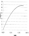
The relation between blade radius (r) and angle (ɵ) is shown in Figure 1. |
Top VOLUTE DESIGN Since the volute converts the kinetic energy of the fluid in to pressure energy, the area from the inlet to outlet is expanding. The governing equation for developing profile of volute is, |
b = an axial width of a volute, |
r= radius of a volute at any given angle Φ of volute |
Hr= head developed by runner |
Selecting trapezoidal cross section of the volute with sides diverging at total angle of 60°, the relation between b and r is established by following relations, |
The axial width of volute at inlet, b0, is obtained by adding appropriate clearance to the axial width of impeller at outlet. |
The value of r’ is assumed as |
So the relation between b and r can be established for the integration purpose, Different values of angle (Φ) for a given radius (r) are obtained by integrating the equation (8) for different values of radius (r). |
Top RESULTS & DISCUSSION The design outcome is summarized in Table 4. |
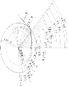
The developed blade profile using Computer Aided Design (CAD) software CATIA [10] is shown in Figure 2. Last three points of the blade profile are corrected to make it practical. |
The blade profile correction in last three points needs to be investigated. Different blade profile can be achieved by varying the factor q in the equation (6). |
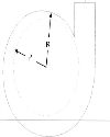
The developed volute profile using Computer Aided Design (CAD) software CATIA [10] is shown in Figure 4. |
Top CONCLUSION CCP has been identified as one of the critical components for fusion research reactor. The requirements of the cryogenic cold circulating pump for future fusion research reactor is understood and its operating regime is decided. The category of turbo machine is selected based on properties of fluid to be handled to start the basic design. Design aspects of hydro-dynamic pump are understood from the fundamental and preliminary basic design of hydro-dynamic parts are carried out; first results are obtained. Design procedure is established for the cold circulating pump design; further optimization of some parameter will be carried out. The design is based on more number of empirical correlation and assumptions, therefore a test of the pump with actual operating conditions must be carried out to get the required design. |
Top ACKNOWLEDGEMENT The authors would like to thank the Project Director of ITER-India, Gandhinagar and Director of SVNIT for their support and encouragement. The views and the opinion expressed herein do not necessarily express those of the ITER organization and the ITER partners. |
Top Figures | Figure 1.: Graph radius (r) v/s Angle (ɵ) for q=1
|  | |
| | Figure 2.: Blade Profile
|  | |
| | Figure 3.: Volute Profile
|  | |
|
Tables | Table 1: The process parameters at the inlet and outlet
| | Parameter | Value | Unit | | Inlet pressure-P2 | 5 | bar | | Inlet temperature-T2 | 4.3 | K | | Inlet density-ρ2 | 139.4 | kg/m3 | | Inlet Enthalpy-h2 | 11710.5 | J/kg | | Inlet Entropy-S2 | 3268.5 | J/kg-K | | Pressure head-∆P | 1.35 | bar | | Mass flow rate-ṁ | 2.21 | kg/s | | Adiabatic efficiency of pump-η | 0.7 | | | Outlet pressure-P1 | 6.35 | bar | | Outlet Entropy (ideal)-S1(ideal) | 3268.5 | J/kg-K | | Outlet Enthalpy (ideal)-h1(ideal) | 12670.8 | ol/kg | | Ideal enthalpy rise-∆h(idoal) | 960.37 | J/kg | | Actual enthalpy rise-∆h(idoal) | 1371.96 | J/kg | | Outlet Enthalpy (actual)-hl (actual) | 13082.43 | J/kg | | Outlet Entropy (actual)-Sl (actual) | 3360.93 | J/kg-K | | Outlet temperature-T1 | 4.51 | K | | Outlet density-ρ1 | 140.39 | kg/m3 | | Power | 3032.034 | Watt |
| | | Table 2: Values of Cm, Q,(β and ɵ at different radial location
| | r | Cm | W | β | ɵ | | 1 | 0.0285 | 9.2 | 34.7 | 15.4 | 0.0 | | 2 | 0.0298 | 9.0 | 32.8 | 15.9 | 8.8 | | 3 | 0.0310 | 8.8 | 31.0 | 16.4 | 16.5 | | 4 | 0.0323 | 8.6 | 29.2 | 17.1 | 23.3 | | 5 | 0.0336 | 8.4 | 27.3 | 17.8 | 29.1 | | 6 | 0.0348 | 8.2 | 25.5 | 18.7 | 34.0 | | 7 | 0.0361 | 8.0 | 23.7 | 19.7 | 37.9 | | 8 | 0.0374 | 7.8 | 21.8 | 20.8 | 40.8 | | 9 | 0.0386 | 7.6 | 20.0 | 22.2 | 42.7 | | 10 | 0.0399 | 7.4 | 18.2 | 23.9 | 43.5 | | 11 | 0.0412 | 7.2 | 16.3 | 26.0 | 43.2 |
| | | Table 3: Variation of radius (R) with angle (Φ)
| | R | Phi(Φ) | | 1 | 0.05 | 60.40017 | | 2 | 0.055 | 111.8126 | | 3 | 0.06 | 169.1547 | | 4 | 0.065 | 231.4761 | | 5 | 0.07 | 298.038 | | 6 | 0.074 | 353.9431 | | 7 | 0.0743 | 358.2231 |
| | | Table 4: Design Output
| | Parameter | Symbol | Result | | Specific speed | nsq | 45 | | Diameter of hub of an impeller | dh | 24 mm | | Diameter of shaft | ds | 20 mm | | Inlet diameter of impeller | D2 | 57 mm | | Blade angle at inlet | β2 | 15.36° | | Number of blades of impeller | Z | 11 | | Meridional velocity at inlet | C2 | 9.18 m/s | | Outlet diameter of impeller | D1 | 83 mm | | Breadth at outlet | B1 | 9 mm | | Blade outlet angle | β1 | 26° | | Outlet velocity | C1 | 7.16 m/s | | Hydraulic efficiency | ηh | 0.858 | | Volumetric efficiency | ηv | 0.95 | | Overall efficiency | ηo | 0.78 | | Power | P | 3 kW |
| |
| | |
|
|
|