|
|
|
|
Motoring test of a stirling cycle engine system while acting as a cooler Shendage D.J.1, Kedare S. B.1, Bapat S. L.1 1Indian Institute of Technology Bombay, Powai, Mumbai-400 076 Abstract A lot of work is done on the Stirling coolers of various configurations at IIT Bombay. This includes the development of nitrogen liquefier, with a capacity of 5–6 liter/h, as a higher capacity cooler to miniature coolers, with capacities as low as 1 W at 80 K, for IR detector cooling onboard satellite. Presently work on “Development of Stirling Engine for 1.5 kW electrical power output” is in progress with the intention of making use of the experience gained in the process. It is of Betatype with rhombic drive mechanism. This paper presents the results of a cooling system which has not been designed as a cooler but has been designed for providing power in the form of an engine. It also discusses the experience during motoring test and initial trials on Beta type Stirling engine with Rhombic drive mechanism as cooler. Initially, the Stirling cycle engine setup is tested ? by welding single tube to the cylinder head and charging at slightly higher pressure than ambient. Further, four tubes are welded to the cylinder head to provide the sufficient flow passage through heat receiving tubes, which was not case with single tube. The condensation at the top of cylinder head and around the tubes is observed in three minutes after starting, with Helium as working fluid and charging pressures of 3.1, 4 and 5 bar. The pressure ratio, which is ratio of the maximum pressure to the minimum pressure in the cycle system, is around 1.72. The system is operated without any substantial load and let some of the dimensional mismatch reduce by way of wearing out unmatched components. Then it is operated repeatedly, in this fashion so that every time the system is restarted, it should need less power. After testing and conducting trials cylinder head is inspected visually. No scratches or rubbing impressions are observed at contact the contact surfaces. Top Keywords Stirling engine, Rhombic drive mechanism, Motoring test. Top | INTRODUCTION Stirling cycle under the ideal conditions can give larger output than Carnot cycle with the same values of the maximum temperature and pressure [1, 2], 1.5 kWe is decided as capacity which will satisfy the requirement of 4–5 households in remote area. The areas are the ones where providing electricity through grid is almost impossible due to long distances in hilly terrains as well as unfavourable economics of infrastructure required for transmission of power due to terrain conditions. |
In the field of development of Stirling coolers of various configurations, a lot of work is done at IIT Bombay. This includes the development of nitrogen liquefier, with a capacity of 5–6 liters/h, as a higher capacity cooler to miniature coolers, with capacities as low as 1 W at 80 K, for IR detector cooling onboard satellite. Both these technologies have been transferred to the sponsoring agencies viz., Department of Science and Technology and ISRO Satellite Centre, Bangalore. Presently work on “Development of Stirling Engine for 1.5 kW electrical power output” is in progress with the intention of making use of the experience gained in the process. It is of Beta-type with Rhombic drive mechanism. |
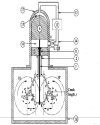
Top BETA-TYPE STIRLING ENGINE WITH RHOMBIC DRIVE MECHANISM Amongst the various configurations the Beta (β) configuration is chosen as it allows for an overlapping volume swept by both the piston and the displacer in the same cylinder [1, 2], This ensures a pressure ratio somewhat higher than the Alpha configuration with same set of strokes and diameters. Further, compared to Gamma configuration it is substantially large under similar conditions as mentioned above. Again from the various drive mechanisms available for Beta systems, the rhombic drive mechanism is chosen as it totally avoids the side thrust against some side thrust in case of the crankshaft connecting rod drive wherein the clearance increases on a specific side leading to substantial increase in leakage rate apart from the wear and tear problems [3,4]. Fig. 1 shows the schematic diagram of the Stirling engine using rhombic drive mechanism. The displacer (6) and the piston (1) reciprocate in the expansion (15) and compression (16) spaces respectively with minimum side thrust. The stroke of the displacer and the piston is same in present case. The stroke is fixed and governed by crank (5, 5’), connecting rods (4, 4’, 9, 9’) and the eccentricity (e). The gear (10, 10’) meshes with each other and rotates in opposite direction of each other. The whole arrangement is symmetric about the centreline of the displacer and the piston including two shafts. One of the shafts can be used for extracting the power output and other for purpose of starting. |
Top OUTLINE OF THE EXPERIMENTAL DESIGN The thermodynamic design of the unit has been finalised wherein the heat source considered will allow the maximum temperature of the working fluid to be raised to 750 K. The heat removal will be with the help oi water as the cooling medium and thus lead to lowest temperature of the working fluid as 350 K. Some of the major dimensions of the unit are given in the Table 1. The use of 750 K as the maximum temperature in the system allows for the use of regularly used materials such as SS304 and SS316 which do not create any problems within this temperature range. The machining and welding methods for the same are also known very well. In present case, eccentricity ratio is restricted up to 1.5 to avoid buckling problem and jerky movements. Hydrogen is chosen as the working fluid due to better thermodynamic and thermo-physical properties. The total mass in the working space is expected to be around 0.8 gram only. This should remove the fear in mind because of hydrogen generally being considered as hazardous working fluid. The heat transfer area has been decided after carrying out experiments to obtain the overall heat transfer coefficient under simulated conditions with air as the working fluid. The heat transfer requirement indicated that about 20 heating tubes will be required to provide the necessary heat transfer to the working fluid. This number of tubes means 40 joints to be tested for leak. In order to ensure that no other joint leaks, it was decided that a cylinder head block be fabricated which will have exactly the same dimensions as the final cylinder head with 20 tubes but initially provide just one tube for connectivity between the working spaces. |
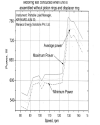
The purpose of fabricating a dummy cylinder head was to ensure that the unit can be operated for the motoring test. Motoring test generally refers to determination of power loss due to frictional losses in the unit when there is no load of compression or expansion on any of the components. To ensure that there is no load, normally in case of a totally sealed unit, the same is evacuated fully and then operated at required speed (rpm). This also allows to increase the speed gradually and not to jump to the design speed in the first instance. If the unit runs smoothly without excessive power consumed in the friction, it gives more confidence to go for higher and higher speed, initially under high vacuum. Fig. 2 shows the power consumed during motoring test at various speed by engine assembly without piston rings and displacer rings, when displacer liner and displacer are assembled first time. Further, it is observed that as the speed increases, fluctuation in the power consumed (i.e. torque required) also increases up to certain speed. |
When a cryocooler is being tested in this fashion, it is mainly undergoing the regular preliminary tests with the type of drive mechanism chosen and one immediately starts getting the performance with variation in parameters. However, when an engine is being tested in this fashion, it does not work in the engine mode where it should generate mechanical power either to be used directly for the purposes of getting mechanical work output e.g., water pumping or operating some machines; but starts working in the cooler mode wherein it will consume power. If this test is carried out under some pressure condition other than vacuum then the power consumed will be sum of the frictional work and the work used for processing the gas through processes such as compression process. If expansion process also is occurring then it will also generate some work and pressure-volume diagram for the total space will give the net work consumed. In the present system, oil is used for the lubrication in the compression process. If evacuation is carried out to high vacuum level, the oil vapour pressure not being too low will continuously evaporate and the composition of oil itself will change. Moreover, we have a shaft seal which will work mainly when the inside pressure is higher than the outside ambient pressure. |
The purpose of the present test is twofold: Operate the system without any substantial load, let some of the dimensional mismatch reduce by way of wearing out unmatched components and operate it in this fashion so that every time the system is restarted, it should need less power. When this power reduction stops it is the indication that the power required is solely due to friction and now the actual motoring test can be carried out at the minimum practical pressure level without affecting the oil charge in the system. |
As this is the first prototype, the fabrication was to be kept simple. The crank-case is made of thick metal plates and welded construction has been used to form the crankcase. As the rhombic drive mechanism was used for the first time, at each stage the partial assembly was decided to be tested using an external three phase motor of the capacity of 1.5 kW. First such run was taken with only the two gears assembled. The next step was to assemble the rhombic drive mechanism and use dummy rod. This was to check whether the movements of piston rod and displacer rods are parallel to each other or not. It was useful in noticing some errors in the fabrication of various components. The gear pump for lubrication was now tested by filling oil in the crank case to the desired level in the sight glass. The splashing of oil on the inner, lower portion of the cylinder liner was also observed. The splashed oil quantity was also sufficient in case the pump does not perform for a short while. After this stage, the compression cylinder block, the cylinder liner and the piston were assembled. Now the displacer rod was passing through the piston and the seal (Piston bush) held in position within the piston. As a more guiding length was now available, the operation became somewhat smoother than earlier and also the movement of the displacer rod was without any side-wise movement. The next step was to assemble the water cooler. The water cooler has vertical slits of fine dimensions through which the compressed gas will pass and form one stream in the heat exchanger. The cooling water passes through the circumferential grooves and forms the other stream. If more heat is to be rejected to water, the external chilling of this water can also be resorted to as in case of Stirling cycle based nitrogen liquefier. Presently, it has been planned that at least during initial testing only tap water at available temperature should be used. Next step was to assemble the regenerator separately and ensure that the proper clearances and dimensions are properly matched. Lastly, the cylinder head with heat transfer tubes which, open up in the expansion space at one end and at the hottest section of the regenerator at the other end. It was clear that as soon as this component is also put in position, the piston and displacer will start experiencing/undergoing some substantial load compared to load experienced till now. Also, the leak test needs to be carried out separately to test the 40 joints coming into picture due to use of 20 tubes. If this is to be done directly after assembly, the minor leaks in other portions of the assembly will not be noticed unless these 40 joints are made leakproof. Hence, it is important to select proper welding method. |
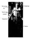
Top ASSEMBLY AND TESTING The activity of making of 40 joints leak proof would involve dissembling the unit quite a few times, mainly because of joining process. It was decided that identical cylinder head block be fabricated with same dimensions and the tolerances but with only one tube connection to link the expansion space with the regenerator high temperature section. At this stage, the pressure test was initially carried out with nitrogen and the pressure setting of the safety valve also could be done by ensuring that it opens if the pressure in the system, for any reason rises beyond preset limit. All the nuts were tightened to complete the assembly and leak test was carried out. At around 30 bar a whistling sound was noticed from the portion where copper shim is used for the sealing purpose. This was used as in this portion of the system as the O-rings of Ethylene-Propylene (EPDM, EPR and EP), Neoprene or Viton etc. will not withstand the higher temperatures. The nuts were further tightened and the whole system was made leak proof for a pressure level of 22 bar but at ambient temperature conditions. Fig. 3 shows the photograph during leak test of a Stirling cycle engine system with N2 as working fluid and charged at 6bar. The unit is now in assembled condition and ready for preliminary testing. It was decided to operate the unit at almost one bar pressure in the system with water flow on compared to 30 bar charge pressure and 20 tubes for the cyclic flow. It is clear that the required flow can take place through the single tube. |
Top RESULTS AND DISCUSSION The unit was operated at the lowest possible speed of 164 rpm and the unit operated for sufficiently large number of cycles to give the feel of the unit operation. The unit was operating without any noise or vibrations but the cylinder head was not getting cooled as per the expectation nor was it getting heated. It was realised that the cylinder block without heater tubes weighs around 16.98 kg and to show any drop in temperature, sufficient cooling must be provided. |
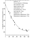
For this purpose, the mass flow needs to be increased and hence the unit was charged at slightly higher than ambient pressure (3.1 bar) and the unit was operated again at minimum possible speed. Now it was observed that the single tube cannot handle the required flow rate and the load on the piston was increasing very quickly leading to the tripping of the motor. Operating under this condition even though for only a few minutes indicated condensation of water vapour in the air on the cylinder head where the thickness was the minimum. The temperature of the whole cylinder block had also slightly dropped and could even be felt by hand. However, it was felt that the unit must be operated at some reasonable speed for which the number of tubes must be increased, the charge pressure should be positive but not very high and now the speed of the system should be increased as the cooling capacity is almost proportional to speed. The number of tubes is increased to four. Then, the pressure is varied as 9, 7, 5, 4, 3.1 bar and power consumed at different speed is observed. It reveals that as the engine speed increases, power factor at the motor increases. During trials at the pressure of 3.1, 4 and 5 bar, condensation at the top of cylinder head and around the tubes was observed in few minutes with pressure ratio around 1.72. The pressure ratio water is greater than before. Fig. 4 shows typical cool down curve, for the charging pressure of 3.1 bar with helium as working fluid. It is observed that motor is tripped because of running in overloading circumstances after 15–20 minute. Therefore, it is not possible to conduct the tests for long run by current motor of 1.5 kW capacity. The liquefier having close dimensions that of present system and operating at 16 bar charge pressure, necessitates motor of 11 kW capacity. |
The next step is to put the cylinder head with the required number of tubes (i.e. 20) and test. Under these conditions the unit will be operated using external motor to test the functioning of the rhombic drive mechanism, and the unit in cooler mode. Walker has given a very good account of the test carried out by Kohler on Philips liquefier to demonstrate the operation of their crankshaft connecting rod driven system to operate as the refrigeration system, as engine and also as heat pump [5], |
As per Walker, if the unit designed as an engine performs well as a cooler, the probability of the unit operating as an engine will be quite high [5]. When the system is operated with external power input and same direction of rotation as required for the engine, it operates as the cooler. Kohler operated their system as cooler and could get nitrogen condensed on the cylinder head [5]. Sufficient quantity was accumulated around the cylinder head portion. The power supply to the motor was then switched off. As soon as this was done, the system started operating as the engine and the direction of rotation changed. This was explained by Kohler stating that the original expansion space now acts as the compression space and the heat of compression can be rejected to the liquid nitrogen pool while comparatively higher temperature original compression space acts as the expansion space and the circulating water tries to maintain the temperature around ambient temperature. Thus, the temperature difference between new expansion space and new compression space is around (300 — 80 = 220 K). This difference is enough to run the system as an engine till the liquid nitrogen pool was totally evaporated. |
Top CONCLUSIONS This paper thus shares the experience during initial trials of Stirling engine as cooler. The functioning of drive mechanism subassembly is ensured during free run test (motor driven) at atmospheric pressure itself. At this time, the drive mechanism, piston and displacer drive rod only was In position. The free movements of various components such as piston, displacer, lubricating oil pump etc. at the different speeds are ensured. The leak test under 22 bar is successfully conducted. With Helium as working fluid and charging pressures of 3.1, 4 and 5 bar, condensation at the top of cylinder head and around the tubes was observed in few minutes after starting with pressure ratio 1.72. |
As per Walker, if the unit designed as an engine performs well as a cooler, the probability of the unit operating as an engine will be quite high. Hence, system is operated for different pressures and speeds as cooler. As an engine, the system needs to be provided heat so as to maintain a temperature of 750 K inside the expansion space. Very few test runs have been carried out and that too at low charging pressure with Helium. |
Top ACKNOWLEDGEMENT The authors acknowledge the financial support from Ministry of New and Renewable Energy, Government of India, to carry out the present work. |
Top Figures | Fig. 1:: Schematic diagram of the Stirling engine using rhombic drive mechanism 1: Piston; 2: Piston rod; 3: Piston yoke; 4, 4’: Connecting rod (for piston yoke); 5, 5‘: Crank; 6: Displacer; 7: Displacer rod; 8: Displacer yoke; 9, 9’: Connecting rod (for displacer yoke);‘10, 10’: Spur Gears; 11: Bush, 12: Regenerator, 13: Multiple heat receiving tubes, 14: Connecting duct, 15: Expansion space, 16: Compression space, 17: Cylinder head, 18: Crankcase, 19: Cooler, 20: Coolant.
|  | |
| | Fig. 2.: Power consumed during motoring test at various speed by engine assembly without piston rings and displacer rings
|  | |
| | Fig. 3.: Photograph during leak test of a Stirling cycle engine system
|  | |
| | Fig. 4.: Cool down curve for Stirling cycle engine system as cooler
|  | |
|
Table | Table 1: Major dimensions of Stirling engine system
| | Parameter | Unit | Value | | Regenerator dead volume | m3 | 58.55 × 10⁻⁶ | | Expansion space swept volume | m3 | 207.65 × 10⁻⁶ | | Regenerator mesh size | per inch | 200 | | Stroke of piston | m | 0.051 | | Stroke of displacer | m | 0.051 | | Bore diameter of piston | m | 0.072 | | Bore diameter of displacer | | m | 0.072 |
| |
| | |
|
|
|